
Vehicle speed change control device

A technology for control devices and vehicles, applied in the direction of engine control, transmission control, components with teeth, etc., can solve the problems of increasing the burden of the synchronization mechanism and prolonging the shifting time

Inactive Publication Date: 2012-02-01
SUZUKI MOTOR CORP
View PDF9 Cites 0 Cited by
  • Summary
  • Abstract
  • Description
  • Claims
  • Application Information

AI Technical Summary

Problems solved by technology

When the rotation speed of the engine output shaft is floating (inconsistent with the rotation speed of the target gear), when the target shift gear is connected to the gear position, the load on the synchronization mechanism is increased mechanically.
In addition, when the clutch connection process is performed with the end of the shift while the engine speed is floating, the engine speed needs to be reduced to the target speed in the half-clutch state, resulting in a problem that the overall shift time is prolonged.

Method used


Image

  • Vehicle speed change control device
  • Vehicle speed change control device
  • Vehicle speed change control device

Examples


Embodiment Construction

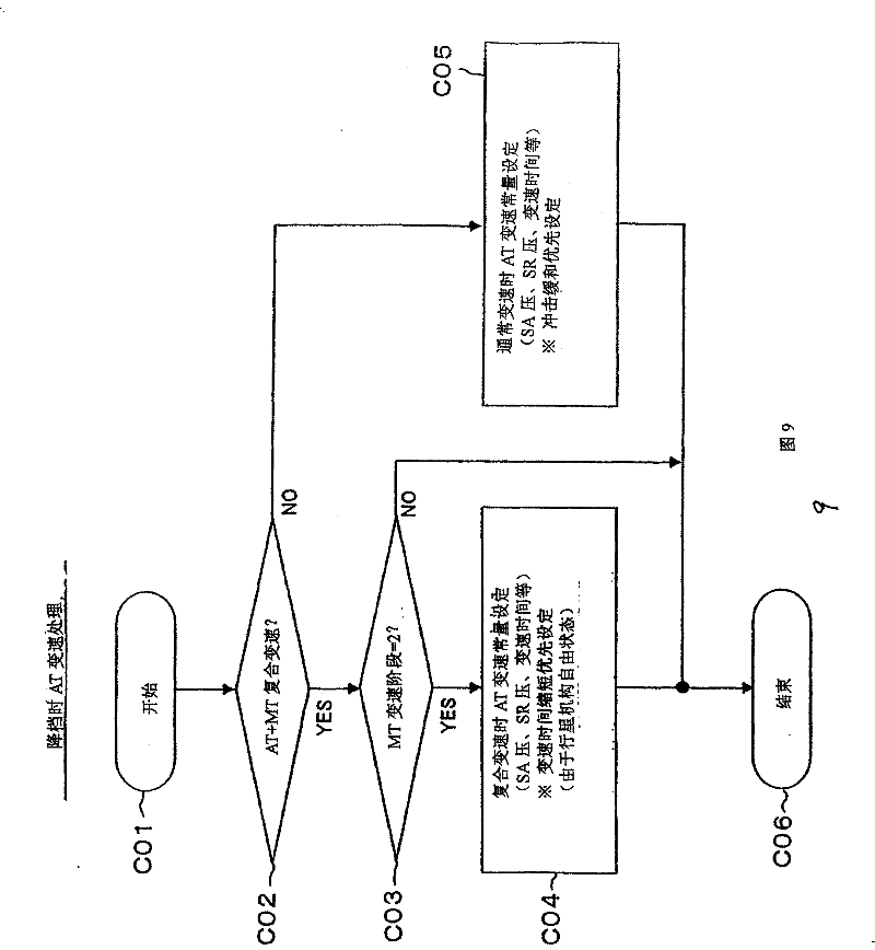
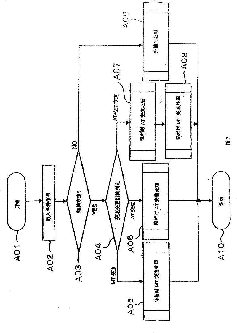
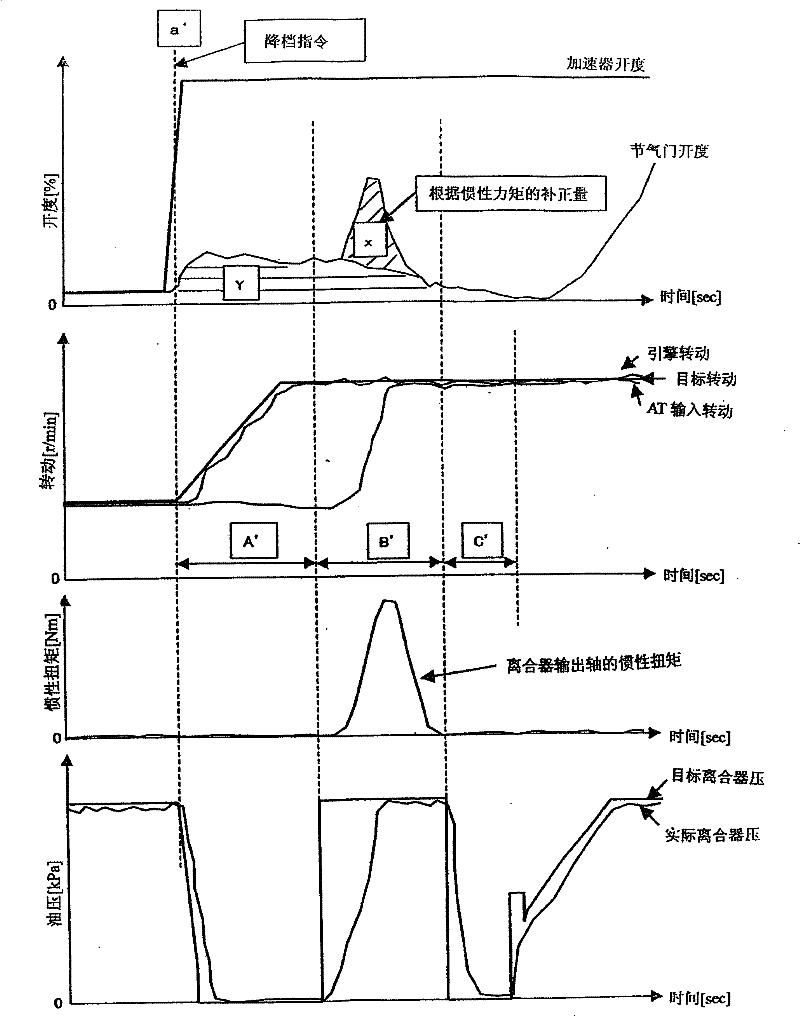
[0045] The embodiments will be described in detail below in conjunction with the accompanying drawings.

[0046] Figure 1-Figure 13 An example of the present invention is shown.

[0047] figure 1 Among them, 1 is the vehicle, and 2 is the power system carried by the vehicle 1. This powertrain 2 includes an internal combustion engine 3 , an automatic transmission (AT+MT) 4 , and a starting clutch 5 as an automatic clutch. Internal combustion engine 3 is connected to automatic transmission 4 via starter clutch 5 .

[0048] The internal combustion engine 3 is provided with: a throttle opening degree control device 7 which is provided with an electronic throttle valve 6 capable of controlling the torque generated by the engine by electronically controlling the degree of opening of the throttle valve; Fuel supply control device 9 for fuel injection valve 8 .

[0049] Automatic transmission 4, the valve body is equipped with a plurality of solenoid valves, and has a plurality...


PUM


Abstract

The present invention relates to a control device for gear shifting of a vehicle, which provides depressing gear shifting performance in which no interruption of drive force is felt in all gears. When the vehicle speed is low, the gear ratio change control is performed by the planetary gear mechanism, and at the high vehicle speed, the gear ratio change control is performed by the constant mesh type transmission mechanism. At this time, the engine-generated torque of the internal combustion engine is controlled while the gear shaft is automatically driven and the automatic clutch is automatically driven, thereby driving and controlling the electronic throttle valve.

Description

technical field [0001] The present invention relates to a speed change control device for a vehicle, particularly a vehicle speed change control device for performing a downshift when a transmission that determines the basic speed ratio of the vehicle as a whole based on the speed ratios of a main transmission and an auxiliary transmission is shifted. . Background technique [0002] The vehicle is equipped with an automatic transmission as a transmission that determines the basic transmission ratio of the vehicle as a whole by changing the transmission ratio of the main transmission and the auxiliary transmission, and a planetary gear mechanism (AT) is provided for the main transmission. The auxiliary transmission is equipped with a constant mesh transmission mechanism (MT), which is equipped with a device that controls the change of the gear ratio of the planetary gear mechanism within a specific speed range, and at the same time controls the change of the speed ratio of th...

Claims


Application Information

Patent Timeline
Patent Type & Authority Patents(China)
IPC IPC(8): F16H61/00F16H61/10F16H59/14B60W10/02B60W10/06B60W10/10B60W30/00B60W10/00B60W10/04B60W10/11F02D29/00F16H59/04F16H59/24F16H59/56F16H59/74F16H61/04F16H61/68F16H61/682F16H63/50
CPCF16H2306/40F16H61/0437B60W10/02F16H61/702B60W10/111B60W10/06F16H63/502B60W30/19F16H2306/54
Inventor 森达治川本润大桥和俊
Owner SUZUKI MOTOR CORP
Learn More