Audio system for outdoor umbrella

an audio system and outdoor umbrella technology, applied in the field of outdoor umbrellas, can solve the problems of difficult mounting of an audio system on the outdoor umbrella, the inability of a portable music player to be mounted to the outdoor umbrella, and the design of a practical audio system

Inactive Publication Date: 2009-03-19
MA
View PDF13 Cites 38 Cited by
  • Summary
  • Abstract
  • Description
  • Claims
  • Application Information

AI Technical Summary

Benefits of technology

[0014]A main object of the present invention is to provide an audio system for an outdoor umbrella, wherein the audio system is adapted to detachably mount to a conventional outdoor umbrella so as to provide an add-on function for the conventional outdoor umbrella without altering its original structure.

Problems solved by technology

However, such portable music player cannot be mounted to the outdoor umbrella.
Actually, mounting an audio system on the outdoors umbrella is a challenging task.
Not to mention the problems arise when one tries to design the mechanical connection between the audio system and the outdoors umbrella without interfering its smooth folding action, it is the problem as how to provide the audio system with enough and convenient power source which simply possesses the main difficulty in designing a practical audio system.
Since the outdoors umbrellas, as the name implies, are designed for use in outdoors, existence of an electrical power source cannot be guaranteed.
Even through there are electrical sources exist, a tedious connection between the audio system and the electrical source is unavoidable in that long wires have to be used.
For some cases, the audio systems may be compatible with portable dynamos, however, bring a bulky dynamo with the outdoor umbrella is not really a wise decision.
Once the electrical connection the audio system is broken, the user is unable to replace the audio system.
In other words, once the audio system is malfunction, the mood of all the participants may be ruined.
The very advantage and convenience of the typical outdoors umbrella, however, do not shelter its disadvantages.
Yet in an outdoors environment, the external power source, at least in the sense of the most typical power source for lighting system—electrical power source, cannot be guaranteed.
One might utilize a rechargeable battery as the power source, but an additional step of charging the battery is inevitably needed.
Very often, charging the battery can only be taken place when the umbrella is idle.
Therefore, for example, when the user of the umbrella forgets charging the battery, the lighting system would not work on the next day.
Sometimes, where the rechargeable battery cannot be conveniently detached from the outdoors umbrella, charging the battery would mean allocating extra space to store or to place the outdoor umbrella while the battery is being recharged.
The mounting arrangement of most of the outdoors umbrellas represents another problem.
A considerable numbers of outdoors umbrellas have their lighting system mounted insecurely or in such a manner that the lighting system is functionally incompatible with the normal operation of the outdoor umbrellas themselves.
As result, the performance of the respective lighting system is far from satisfactory.
For example, during folding and unfolding operations of the outdoors umbrella, the awning ribs thereof may accidentally destroy the illuminating units of the lighting system.
If the lighting system is so insecure that, when subject to certain outdoors phenomenon, such as against a sudden strong wind, the lighting system is incapable of safely or unstably operating, it would not only cause disruption to the activities in which it uses, but also harm to the users, especially those standing or sitting within the lighting zone.
As a result, where the outdoors umbrella needs to be inclinedly supported on the ground in order to shield a particular direction, or partially opened for a particular purpose, the lighting system could not be satisfactorily operated.

Method used


Image

  • Audio system for outdoor umbrella
  • Audio system for outdoor umbrella
  • Audio system for outdoor umbrella

Examples


third embodiment

[0150]The power unit 31A comprises a power outlet 311A provided on the supporting shaft 21A to electrically extend from the illuminating units 32A, an extension cable 312A electrically extended from the power outlet 311A for electrically plugging into an external power source, and a power switch 313A provided on the supporting shaft 21A to control the illuminating units 32A in an on and off manner. It is worth to mention that the power unit 31A comprises a transformer to convert an AC power from the external power source into a desired DC power for the illuminating units 32A.

[0151]As shown in FIG. 15, the illuminating units 32A are mounted to the awning arms 11A respectively, wherein each of the illuminating units 32A comprises a plurality of illuminators 321A spacedly mounted along the respective awning arm 11A and an extension wire 322A extended along the respective awning arm 11A to electrically connect the illuminators 321A with the power unit 31A.

[0152]As shown in FIG. 15, eac...

fifth embodiment

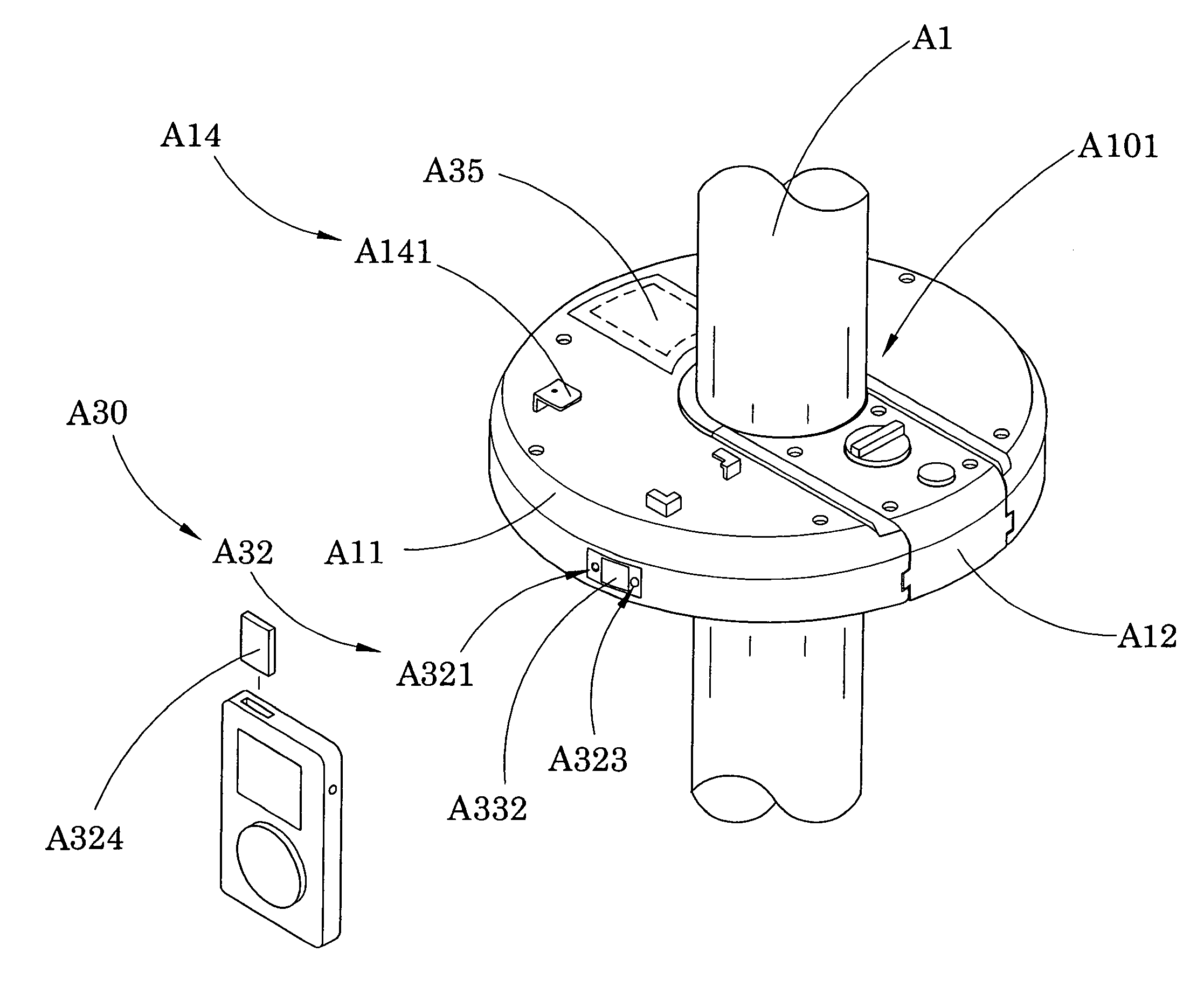
[0180] the first housing body A11, having a U-shaped structure, has two inner guiding walls A111 defining a guiding channel A112 therebetween. The second housing body A12, having a corresponding elongated shape, has two outer guiding walls A121 engaging with the inner guiding walls A111 of the first housing body A11. When the first and second housing bodies 11, 12 are mounted with each other, the audio housing A11 is formed to have a donut shape and to define the mounting slot at a center of the audio housing A10.

[0181]The guiding channel A112 has a closed end defining the mounting slot A101 thereat and an opened end arranged when the second housing body A12 is slidably mounted to the first housing body A11 along the guiding channel A101 through the opened end thereof, the mounting slot A101 is formed at the closed end of the guiding channel A112. In other words, the mounting slot A101 is formed by the closed end of the guiding channel A112 and the inner side of the second housing b...

sixth embodiment

[0222]The audio system, further comprises an adjustable retainer A40′ for adjusting the size of the mounting slot A101′ for the shaft A1 of the outdoor umbrella. The adjustable retainer A40′ comprises a retention arm A41′ having a pusher surface A410′ facing towards the mounting slot A101′ and a control portion A411′ rotatably coupling with the second housing body A12′ such that when the control portion A411′ is driven to rotate, the pusher surface A410′ is adjustably move to adjust the size of the mounting slot A101′. As shown in FIG. 28, the control portion A411′ of the retention arm A41′ has an outer threaded portion engaging with an inner threaded portion of a sidewall of the second housing body A12′. The adjustable retainer A40′ further comprises a compression spring A42′ coaxially mounted at the retention arm A41′ for applying an urging force against the retention arm A41′ to push the pusher surface A410′ away from the mounting slot A101′. In other words, when the control por...


PUM


Abstract

An outdoor umbrella includes an umbrella frame and an audio system. The umbrella includes a supporting frame and an awning frame supported by the supporting frame to define a shadowing area under the awning frame. The audio system includes at least a speaker unit supported by the umbrella frame and an audio input operatively linked to the speaker unit such that when the audio input sends an audio signal to the speaker unit, the speaker unit is adapted for producing audio effect within the shadowing area as an additional function for the outdoor umbrella.

Description

CROSS REFERENCE OF RELATED APPLICATION[0001]This is a Continuation-In-Part application of three non-provisional applications. The first non-provisional application has an application Ser. No. 10 / 844,601 and a filing date of May 11, 2004, which is a Continuation-In-Part application of a non-provisional application having an application Ser. No. 10 / 436,192 and a filing date of May 12, 2003. The second non-provisional application has an application Ser. No. 11 / 796,264 and a filing date of Apr. 27, 2007. The third non-provisional application has an application Ser. No. 11 / 147,781 and a filing date of Jun. 7, 2005.BACKGROUND OF THE PRESENT INVENTION[0002]1. Field of Invention[0003]The present invention relates to an outdoors umbrella, and more particularly to an outdoors umbrella incorporated with an audio system for providing an add-on function of the outdoors umbrella.[0004]2. Description of Related Arts[0005]Outdoors umbrellas are set up in many places such as in beach areas, in patio...

Claims


Application Information

Patent Timeline
Patent Type & Authority Applications(United States)
IPC IPC(8): A45B3/00
CPCA45B2200/1009A45B2200/1027F21V21/34F21V33/006F21W2131/10A45B2023/005H04R1/026A45B3/00A45B3/04A45B2023/0012F21Y2101/02F21Y2115/10
Inventor LI, WANDA YING
Owner MA
Why Eureka
Try Eureka