

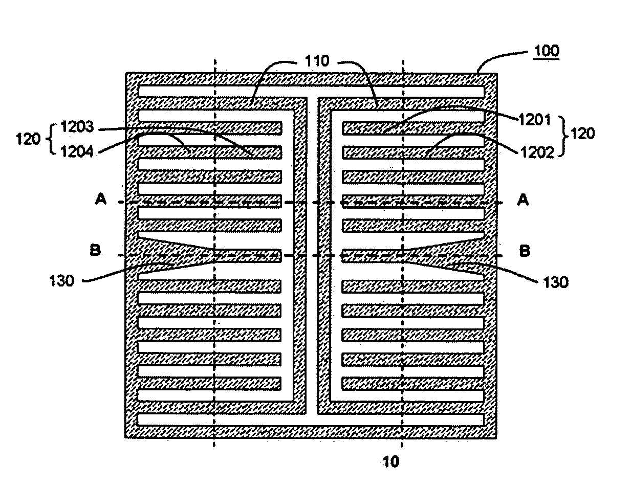
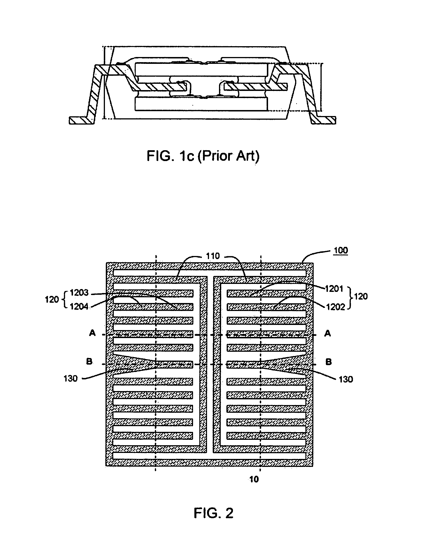
Multi-Chip Stacked Package Structure
a technology of integrated circuits and package structures, which is applied in the direction of electrical equipment, semiconductor devices, semiconductor/solid-state device details, etc., can solve the problems of easy loosening of chips, difficult stacking of chips, and insufficient adhesive area between chips and lead frames, so as to enhance the reliability of chips
- Summary
- Abstract
- Description
- Claims
- Application Information
AI Technical Summary
Benefits of technology
Problems solved by technology
Method used
Image

Examples
Embodiment Construction
[0022]The detailed description of the present invention will be discussed in the following embodiments, which are not intended to limit the scope of the present invention, but can be adapted for other applications. While drawings are illustrated in details, it is appreciated that the quantity of the disclosed components may be greater or less than that disclosed, except expressly restricting the amount of the components.
[0023]In the semiconductor package process, the wafer is doing a thinning process after the front end process to thin the size of the chip between 2˜20 mils. A coating or printing process is used to coat or print a polymer on the bottom of the chip. The polymer is made by a resin or a B-Stage resin. A baking or photo-lighting process is used to let the polymer be a semi-glue material. Then a removable tape is used to stick on the polymer and the wafer sawing process is used to saw the wafer into several dies. Therefore, each of the dies is connected to the substrate ...
PUM
 Abstract
Description
Claims
Application Information