Photostructured imaging display panels

a display panel and photostructure technology, applied in the field of display monitors and photostructured glass/ceramic materials, can solve the problems of degrading image quality, difficult to read in sunlight, poor viewing experience of notebook computer displays and other portable displays, etc., and achieves simple parallax, reduce the field of view, and maintain image quality

Active Publication Date: 2009-03-19
THE AEROSPACE CORPORATION
View PDF6 Cites 17 Cited by
  • Summary
  • Abstract
  • Description
  • Claims
  • Application Information

AI Technical Summary

Benefits of technology

[0012]The present invention is directed to photostructured screens and associated displays using photocerams for creating integrated light baffles in the screen. The pixelized baffling of the screen can be used to reduce the field of view for privacy viewing in crowded environments. Each pixel has a baffle that serves as a simple parallax barrier without lenslets and without resulting interference patterns. As such, special polarized viewing glasses are not required for viewing. In a preferred form, alternating rows of baffled pixels provide stereoscopic viewing.
[0013]The pixelized baffled photostructured screens maintain image quality by integrating the optical baffles directly into the glass display screen. Optical baffles are created w...

Problems solved by technology

Notebook computer displays and other portable displays provide poor viewing under bright ambient light conditions and are difficult to read in sunlight.
Plastic add-on privacy screens are available, but they degrade image quality and are not robust enough for outdoor applications such as ATMs.
The add-on optical films suffer from image degradation due to the inability to accurately align externally applied baffles with individual pixels whi...

Method used


Image

  • Photostructured imaging display panels
  • Photostructured imaging display panels
  • Photostructured imaging display panels

Examples


Embodiment Construction

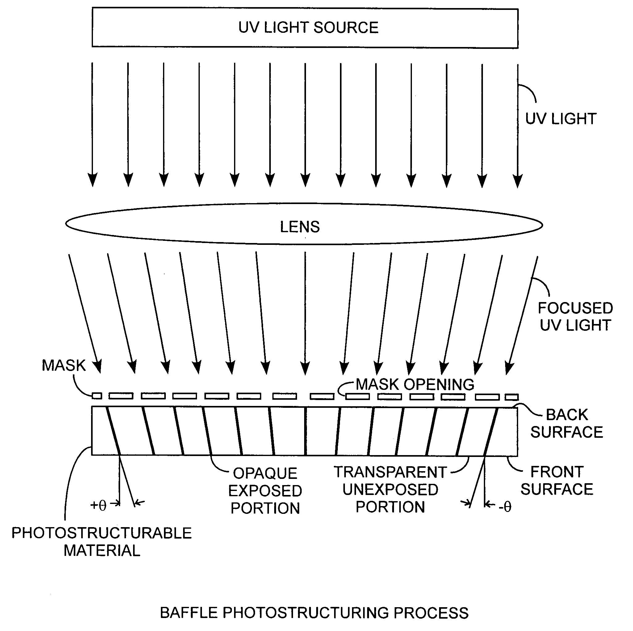
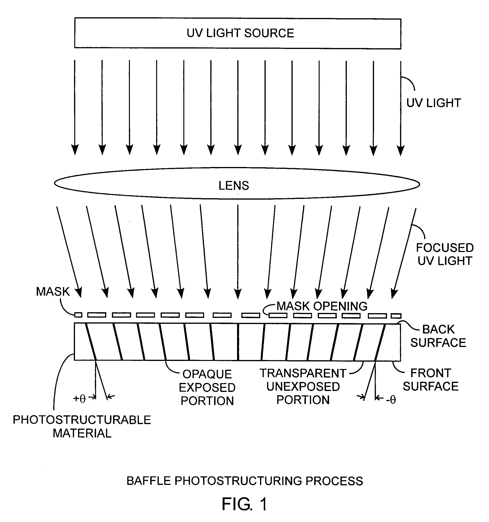
[0019]An embodiment of the invention is described with reference to the figures using reference designations as shown in the figures. Referring to FIG. 1, an ultraviolet (UV) source provides UV light directed toward a lens that then provides focused UV light upon a mask. The mask has a series of openings. The mask openings pass collimated focused UV light upon a photostructurable material. The collimated focused UV light through the mask openings creates an opaque exposed portion after the development using a baking photoceram process. Hence, the series of mask openings creates a series of opaque exposed portions in the photostructurable material. Due to the direction of the focused collimated UV light, the corresponding opaque exposed portions, which are baffles, are angled baffles. As shown in the preferred form, the angles of the baffles are aligned to the focused light so that angles of the baffles on the ends of the material are equal but opposite and tending to zero in the cen...


PUM


Abstract

Photostructurable glass and ceramic materials in slabs are processed into pixelized screens having opaque baffles therein for defining therebetween light pipes in the material through which pixel light is passed and directed with limited fields of view and for stereoscopic viewing, the screens being made using various manufacturing processes included focused UV light exposure and baking of the photostructurable material.

Description

FIELD OF THE INVENTION [0001]The invention relates to the field of display monitors and photostructured glass / ceramic materials. More particularly, the invention is related to photostructured display panels having photostructured screens for adjusting fields of views.BACKGROUND OF THE INVENTION [0002]Photostructurable glass and ceramic materials that are known as photocerams, can be selectively converted from the glass to metasilicate or ceramic state through exposure to ultraviolet (UV) light followed by baking. The process is a basic expose and bake process. The virgin state is visibly clear glass, the unexposed and baked regions remain visibly clear, and the exposed and baked states become optically dark. These dark regions are in a semi-crystalline metasilicate phase or a full ceramic phase. Formation of the full ceramic phase requires baking to a higher temperature. The exposure process is typically done using a UV lamp with a photomask, or more recently, using a laser direct-w...

Claims


Application Information

Patent Timeline
IPC IPC(8): G09G3/20G02B30/32G02B30/60
CPCG02B27/2214Y10T428/24314H04N13/0409G02B27/2242H04N13/31G02B30/36G02B30/32G02B30/27
Inventor JANSON, SIEGFRIED W.ABRAHAM, MARGARET
Owner THE AEROSPACE CORPORATION
Why Eureka
Try Eureka