Charging device and image forming apparatus using the same

a charging device and image forming technology, applied in the direction of electrographic process apparatus, instruments, corona discharge, etc., can solve the problems of degrading printing quality, user still experiences inconvenience, defective image output, etc., and achieve the effect of reducing the ripple of the charging member and the charging member

a charging device and image forming technology, applied in the direction of electrographic process apparatus, instruments, corona discharge, etc., can solve the problems of degrading printing quality, user still experiences inconvenience, defective image output, etc., and achieve the effect of reducing the ripple of the charging member and the charging member

US20090074443A1Active Publication Date: 2009-03-19HEWLETT PACKARD DEV CO LP

Image

  • Charging device and image forming apparatus using the same
  • Charging device and image forming apparatus using the same
  • Charging device and image forming apparatus using the same

Examples


Embodiment Construction

[0043]Reference will now be made in detail to the embodiments of the present general inventive concept, examples of which are illustrated in the accompanying drawings, wherein like reference numerals refer to the like elements throughout. The embodiments are described below in order to explain the present general inventive concept by referring to the figures.

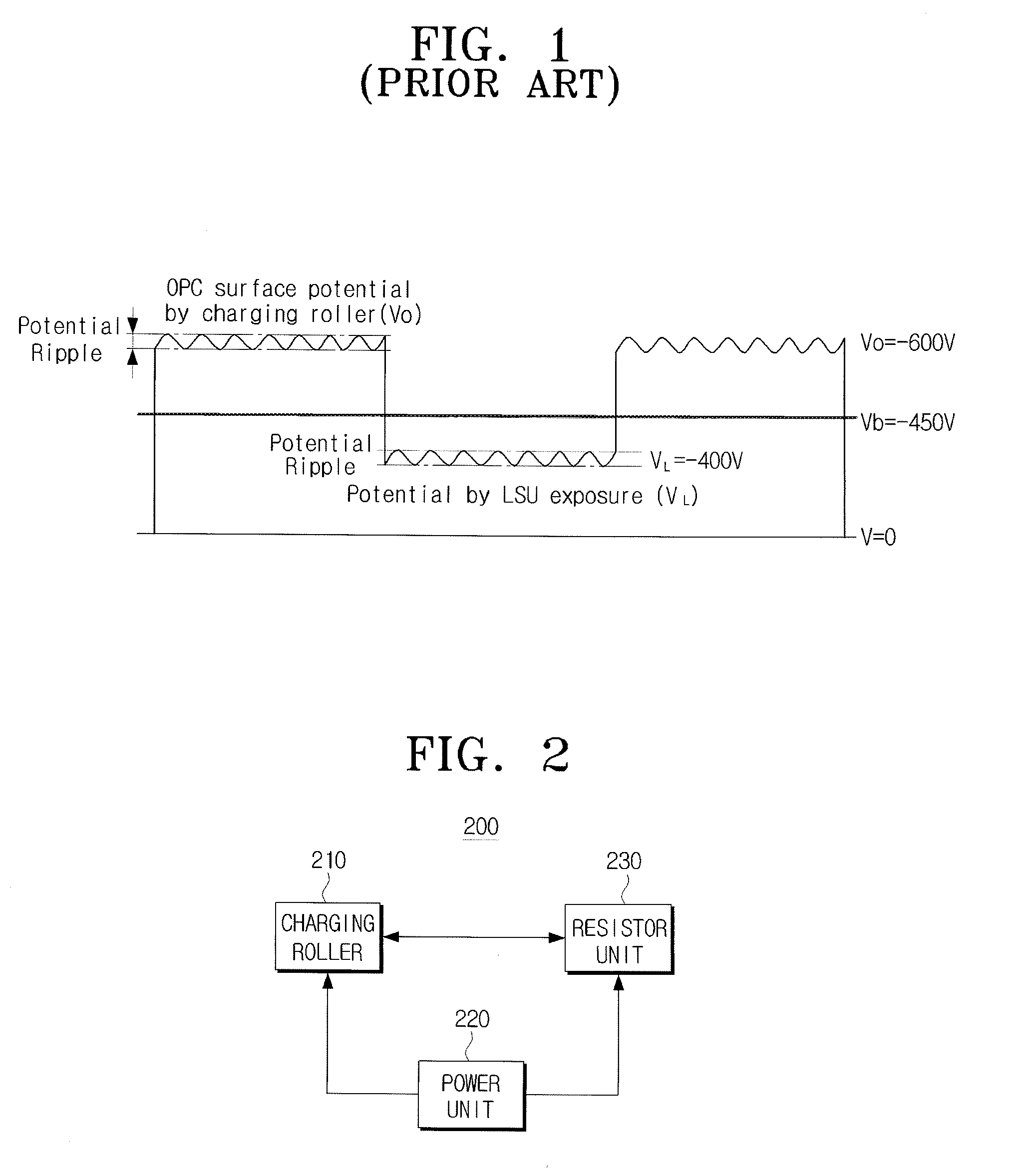
[0044]FIG. 2 is a block diagram illustrating a charging device according to an exemplary embodiment of the present general inventive concept.

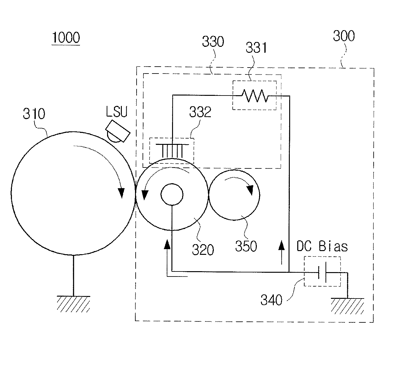
[0045]The charging device may include a charging member 210, a power unit 220, and a resistor unit 230.

[0046]The charging member 210 charges a photosensitive drum (not illustrated) that is used as a photoconductive medium, at a predetermined potential. In specific, the charging member 210 is in contact with a surface of the photosensitive drum, thereby maintaining a nip area on a contacting portion. The power is supplied to a roller shaft of the charging member 210 to charge the photosensit...


PUM


Abstract

A charging apparatus includes a charging member to charge a surface of a photoconductive medium, a power unit to supply an electric power as a bias voltage to the charging member, and a resistor unit to reduce a ripple on the surface of the charging member. Accordingly, a stability of the charging apparatus is secured without using a separate power device.

Description

CROSS-REFERENCE TO RELATED APPLICATIONS[0001]This application claims priority under 35 U.S.C. § 119 (a) from Korean Patent Application No. 10-2007-0093670, filed on Sep. 14, 2007, in the Korean Intellectual Property Office, the disclosure of which is incorporated herein by reference in its entirety.BACKGROUND OF THE INVENTION[0002]1. Field of the Invention[0003]The present general inventive concept relates to a charging device and an image forming apparatus using the same, and more particularly, to a charging device capable of stabilizing a charging potential, and an image forming apparatus using the same.[0004]2. Description of the Related Art[0005]Various types of image forming apparatus are available to form an image on a medium, and these are mainly categorized according to a printing method into a dot printer, an inkjet printer, and a laser printer. The laser printer is superior to the dot printer or the inkjet printer, in that it has a faster printing speed, and better printin...

Claims


Application Information

Patent Timeline
19 Mar 2009
Publication
US20090074443A1
IPC
G03G15/02
CPC
G03G2215/025; G03G15/0283; G03G15/02
Inventors
CHOI, JEONG-JAI