
Developing unit and image forming apparatus having the same

a technology of developing unit and image forming apparatus, which is applied in the direction of electrographic process apparatus, instruments, optics, etc., can solve the problems of increasing the pressure of developer particles, affecting the quality of the developing unit, and the inability to check whether the developing unit is of inferior quality, so as to improve the structure, prevent the developer from being scattered, and evenly spread the pressure of the developer stored

Active Publication Date: 2009-03-19
HEWLETT PACKARD DEV CO LP
View PDF8 Cites 9 Cited by
  • Summary
  • Abstract
  • Description
  • Claims
  • Application Information

AI Technical Summary

Benefits of technology

[0012]The present general inventive concept provides a developing unit which has an improved structure to evenly spread a pressure of developer stored in the developing unit and to prevent the developer from being scattered.
[0013]The present general inventive concept also provides an image forming apparatus having the developing unit in which it is possible to perform printing smoothly.
[0016]When the blocking member is detached from the developing unit, the first section may be connected to the second section, so that a pressure of the developer inside the developer housing may be spread evenly.
[0023]The foregoing and / or other aspects and utilities of the present general inventive concept may also be achieved by providing a developing unit including a developer housing including a first section and a second section, and a blocking member removably disposed between the first section and second section, such that when the blocking member is removed from the developing unit, developer stored in one of the first section and the second section is free to move to the other one of the first section or second section to reduce the pressure of the developer within the one of the first section or the second section.

Problems solved by technology

In the case of a developing unit in which developer is not pre-supplied to developer housings, it is impossible to check whether the developing unit is of inferior quality after the developing unit has been manufactured, since there is no developer in the developing unit with which to perform a print test.
However, problems may arise during distribution before the developing units reach customers.
Accordingly, the pressure of the developer particles may increase, and the torque required to transfer the developer particles may increase excessively due to the coagulated developer particles.
Therefore, the load on a motor may become excessive, causing the motor to be unable to rotate, and making it impossible for printing to be performed.
Such a difference in air pressure may cause a greater amount of developer to be scattered, and an image forming apparatus and printing media may thus be contaminated due to the scattered developer.
If a developing unit is attached to an image forming apparatus, there is a small possibility that fine developer particles flow out.
However, since shocks or vibrations may be applied to the developing unit during distribution before the developing units reach customers, the outflow of fine developer particles may increase.

Method used


Image

  • Developing unit and image forming apparatus having the same
  • Developing unit and image forming apparatus having the same
  • Developing unit and image forming apparatus having the same

Examples


Embodiment Construction

[0034]Reference will now be made in detail to the embodiments of the present general inventive concept, examples of which are illustrated in the accompanying drawings, wherein like reference numerals refer to the like elements throughout. The embodiments are described below in order to explain the present general inventive concept by referring to the figures.

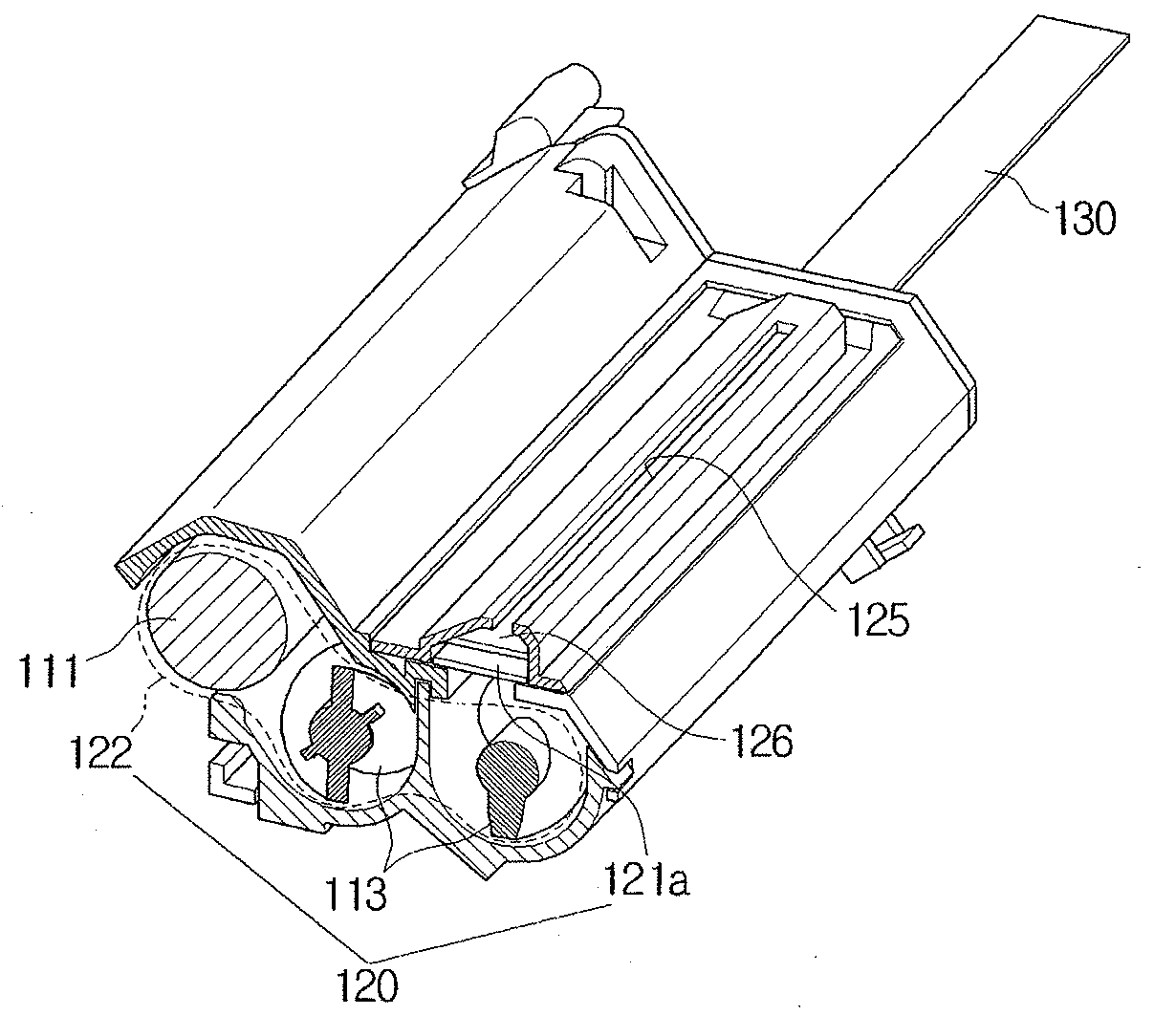
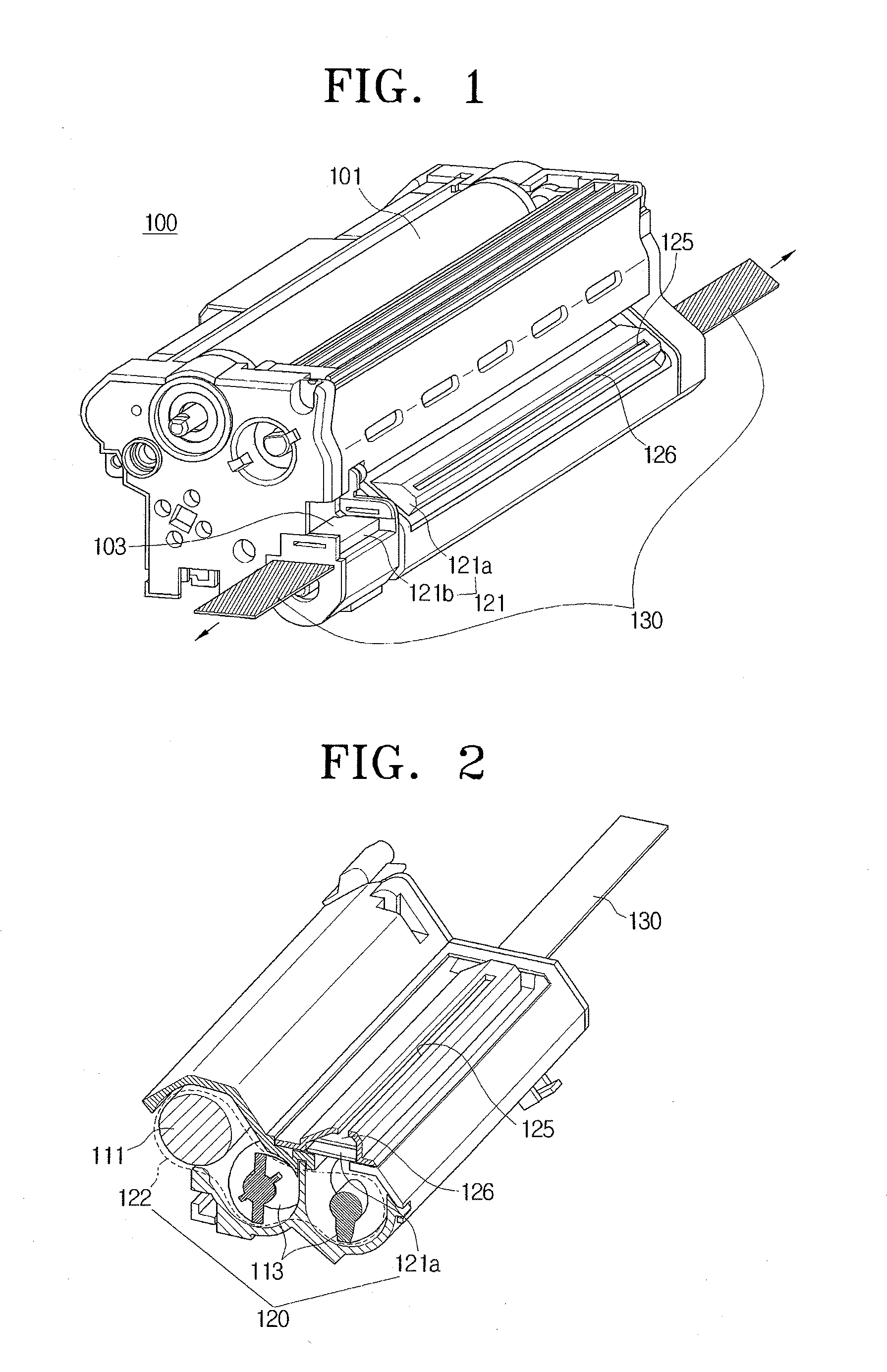
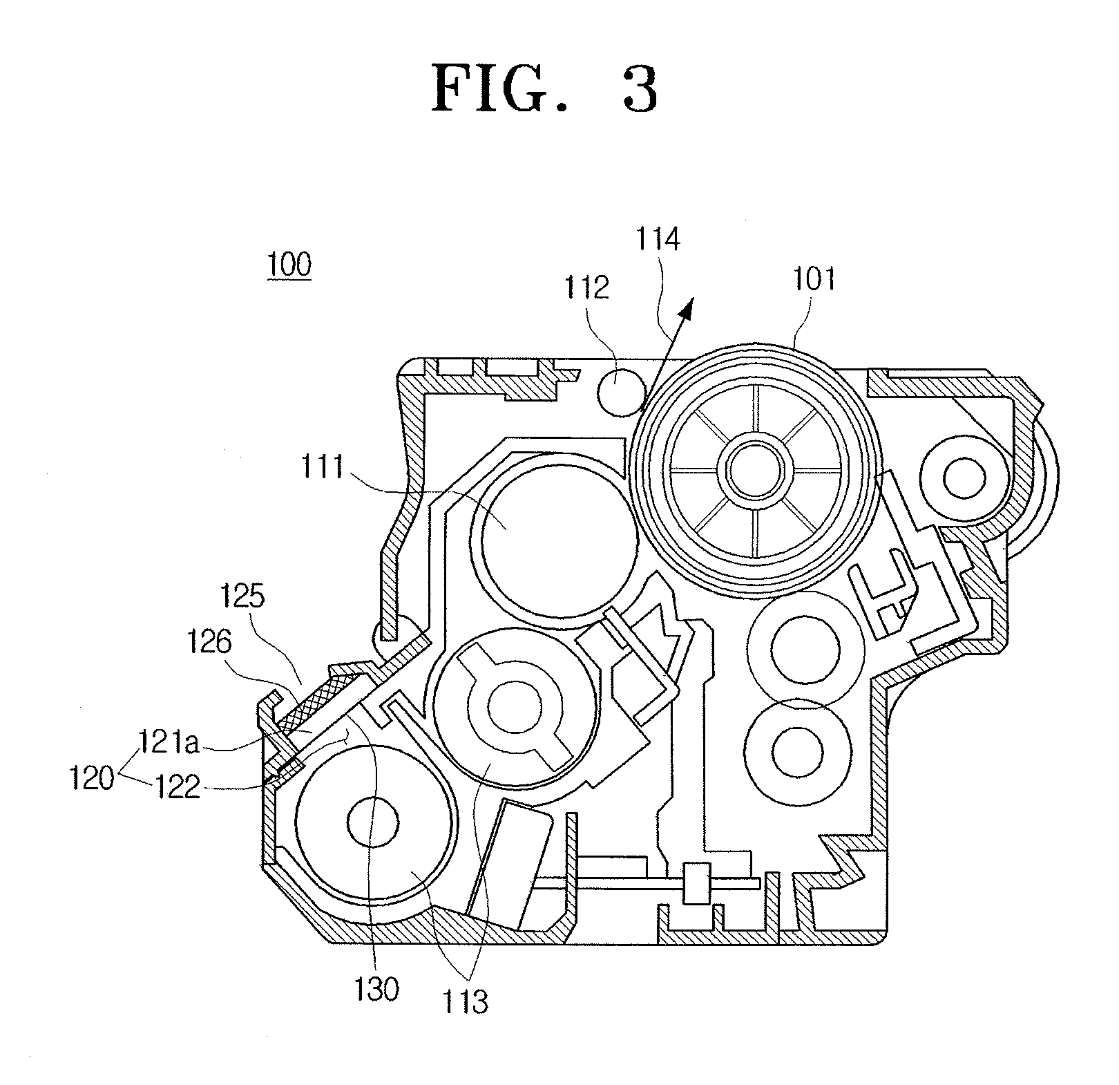
[0035]FIG. 1 is a perspective view illustrating a developing unit 100 according to an exemplary embodiment of the present general inventive concept, FIG. 2 is a fragmentary perspective view illustrating the developing unit 100, and FIG. 3 is a cross-sectional view illustrating the developing unit 100.

[0036]In this exemplary embodiment, the developing unit 100 includes a photosensitive medium 101, a developing member 111, a scatter preventing member 112, a developer housing 120 and blocking members 130. The developing unit 100 according to the above exemplary embodiment employs a tandem method for convenience of description, but ...


PUM


Abstract

A developing unit capable of dispersing a pressure of developer used therein includes a developer housing to contain the developer and a blocking member to divide the developer housing into a first section and a second section, the second section including a developing member disposed therein to transfer the developer onto a photosensitive medium and to store the developer, the blocking member being detachably mounted in the developing unit. When the blocking member is detached from the developing unit, the first section is connected to the second section, so that the pressure of developer inside the developer housing can be spread evenly.

Description

CROSS-REFERENCE TO RELATED APPLICATIONS[0001]This application claims priority under 35 U.S.C. §119 (a) of Korean Patent Application Nos. 10-2007-0093892, filed on Sep. 14, 2007, and 10-2008-0025617, filed on Mar. 19, 2008, in the Korean Intellectual Property Office, the disclosure of which is incorporated herein by reference in its entirety.BACKGROUND OF THE INVENTION[0002]1. Field of the Invention[0003]The present general inventive concept relates to an image forming apparatus utilizing an electrophotographic process, and more particularly, to a developing unit capable of evenly spreading pressure of a developer and preventing the developer from being scattered, and an image forming apparatus having the developing unit.[0004]2. Description of the Related Art[0005]Image forming apparatuses utilizing electrophotographic processes perform operations such as charging, exposing, developing, transferring and fixing in order to form images. Developing units within the image forming appara...

Claims


Application Information

Patent Timeline
IPC IPC(8): G03G15/08
CPCG03G15/0898G03G21/181G03G15/0855G03G15/0865G03G15/0893
Inventor KWON, SE-ILJEON, IN-CHEOL
Owner HEWLETT PACKARD DEV CO LP
Learn More