Belt Rotating Device and Image Forming Apparatus

a rotating device and belt technology, applied in the direction of electrographic process equipment, instruments, optics, etc., can solve the problems of bending fatigue on the end surface of the conveyance belt, damage to the conveyance belt, etc., to reduce the occurrence of belt breakage and improve durability

Inactive Publication Date: 2009-03-19
OKI DATA CORP
View PDF5 Cites 43 Cited by
  • Summary
  • Abstract
  • Description
  • Claims
  • Application Information

AI Technical Summary

Problems solved by technology

However, in the image forming apparatus, when an approaching force caused by that the conveyance belt approaches the regulation board and slides on the regulation board acts greatly, because the frictional force between the contact surfaces of the regulation board and the conveyance belt becomes great, a flexion fatigue occurs on the end surface of the conveyance belt and the conveyance belt is damaged.

Method used


Image

  • Belt Rotating Device and Image Forming Apparatus
  • Belt Rotating Device and Image Forming Apparatus
  • Belt Rotating Device and Image Forming Apparatus

Examples


embodiment 1

Effect of Embodiment 1

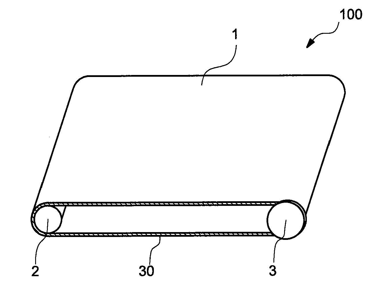
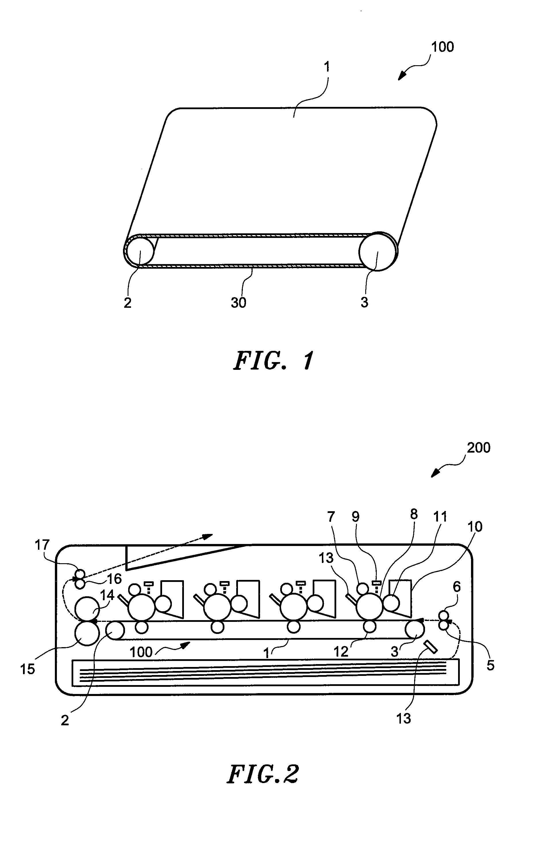
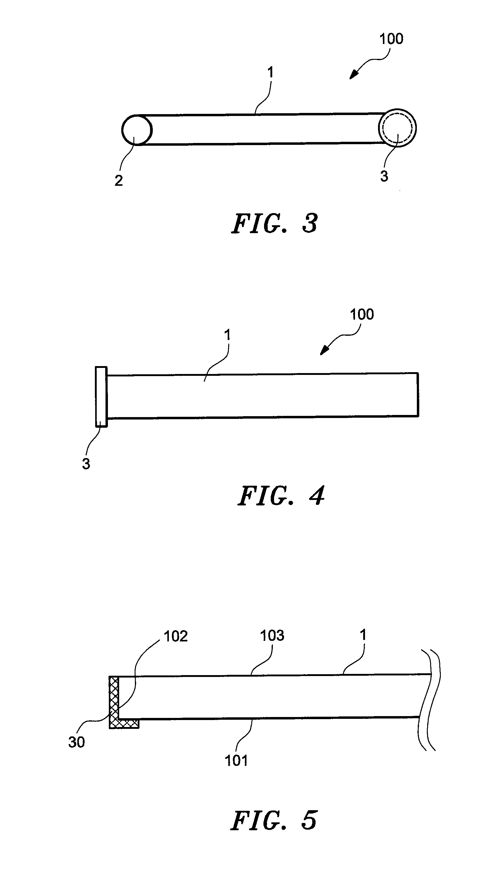
[0091]According to the image forming apparatus 200 of the embodiment 1 of the present invention, through having the endless belt 1 that is coated with the friction reduction agent 30 on the one end surface 102 of the endless belt 1 and the end part of the one end surface 102 side of the inner surface 101, it is possible to improve the durability with respect to the flexion fatigue of the endless belt 1 and to reduce the occurrence of the breakage of the endless belt 1.

Embodiment 2

[0092]FIG. 14 is an explanatory diagram for showing a main part of a belt rotating device in embodiment 2.

[0093]In a belt rotating device 100a of embodiment 2 of the present invention, instead of the friction reduction agent 30 that was used to coat the endless belt 1 in the belt rotating device 100 of the embodiment 1, a friction reduction agent 30a is used to coat the endless belt 1, the friction reduction agent 30a has a paint film hardness that is set on the basis of the durability...

embodiment 2

Effect of Embodiment 2

[0114]According to the image forming apparatus of the embodiment 2, through correctly controlling the hardness of the paint film of the friction reduction agent 30a on the one end surface 102 of the endless belt 1 and on the end part of the inner surface 101 at the side of the one end surface 102, it is possible to improve the durability with respect to the flexion fatigue of the endless belt 1 comparing with the image forming apparatus 200 of the embodiment 1 and to reduce the occurrence of the breakage of the endless belt 1.

[0115]FIG. 11 is a front diagram for showing a structure of a belt rotating device; and FIG. 12 is a structure diagram of an image forming apparatus when it is a printer in embodiment 2.

[0116]Moreover, in the embodiment of the present invention, regarding the endless belt 1, the flange 3 and the friction reduction agent 30 that are used in the above-mentioned image forming apparatus 200 (FIG. 2) of tandem system and the belt rotating devic...


PUM


Abstract

A belt rotating apparatus capable of improving a durability with respect to flexion fatigue of a belt and capable of reducing the occurrence of the breakage of the belt; and an image forming apparatus having the belt rotating device are supplied. The belt rotating device includes a belt that is wound on a roller driven by a predetermined driving means; and a meander prevention member that is slidably contacted with an end surface of the belt for preventing a meander of the belt. In the belt rotating device, a friction reduction agent for reducing slide friction with respect to the meander prevention member is used to coat at least an end surface of the belt.

Description

FIELD OF THE INVENTION[0001]1. Field of the Invention[0002]The invention relates to a belt rotating device to rotate a belt and an image forming apparatus having the belt rotating device.BACKGROUND OF THE INVENTION[0003]Conventionally, a kind of the image forming apparatus is proposed, for example, as disclosed in a patent document 1 mentioned below, which has a belt rotating device that is wound on a driving roller and a rotation supporting member to rotate a conveyance belt conveying a print medium. The image forming apparatus forms toner images of respective colors of yellow, magenta, cyan and black on respective image carrying bodies, and transfers these toner images one by one on the print medium by the movement of the conveyance belt.[0004]Then, in the image forming apparatus, in order to prevent color deviation of the toner images that were transferred on the print medium, that is caused by the meander of the conveyance belt, a regulation board is furnished on one end surface...

Claims


Application Information

Patent Timeline
Patent Type & Authority Applications(United States)
IPC IPC(8): G03G15/00
CPCG03G15/00G03G2215/00151G03G15/1615G03G15/161G03G2215/00168
Inventor ITO, MICHIAKI
Owner OKI DATA CORP
Why Eureka
Try Eureka