Rotary machine cooling system

a cooling system and rotary machine technology, applied in machines/engines, positive displacement liquid engines, pumping machines, etc., can solve the problems of reducing machine efficiency, reducing the efficiency of machines, and generating a significant amount of heat during operation of electromechanical rotary machines such as electric motors or generators, so as to reduce the amount of air, reduce power consumption, and minimize the size of cooling ducts

Active Publication Date: 2007-01-09
SUNDYNE LLC
View PDF29 Cites 32 Cited by
  • Summary
  • Abstract
  • Description
  • Claims
  • Application Information

AI Technical Summary

Benefits of technology

[0007]The present invention provides a rotary machine cooling system that includes a housing having an inlet and outlet. A rotor is supported in the housing for rotation about an axis with the rotor including an outer surface. A stator is disposed within the housing about the rotor having an inner surface adjacent to the outer surface of the rotor. A gap is formed between the inner and outer surfaces sufficient to permit convection cooling. The gap is in fluid communication with the inlet and outlet, and a pumping device pumps a cooling gas from the inlet into the gap and through said outlet. The pumping device includes an impeller affixed to an end portion of the rotor to

Problems solved by technology

Electromechanical rotary machines, such as electric motors or generators, may generate a significant amount of heat during their operation.
This heat generation comes from two major sources, electrical losses and friction losses.
At very high rotation speeds, friction losses become dominant.
These losses cause reduced machine efficiency, and when dissipated in heat, they result in high temperatures.
Speeds can be limited by the temperature capabilities of the materials of construction.
This liquid cooling device and method may be insufficient at times. H

Method used


Image

  • Rotary machine cooling system
  • Rotary machine cooling system
  • Rotary machine cooling system

Examples


Embodiment Construction

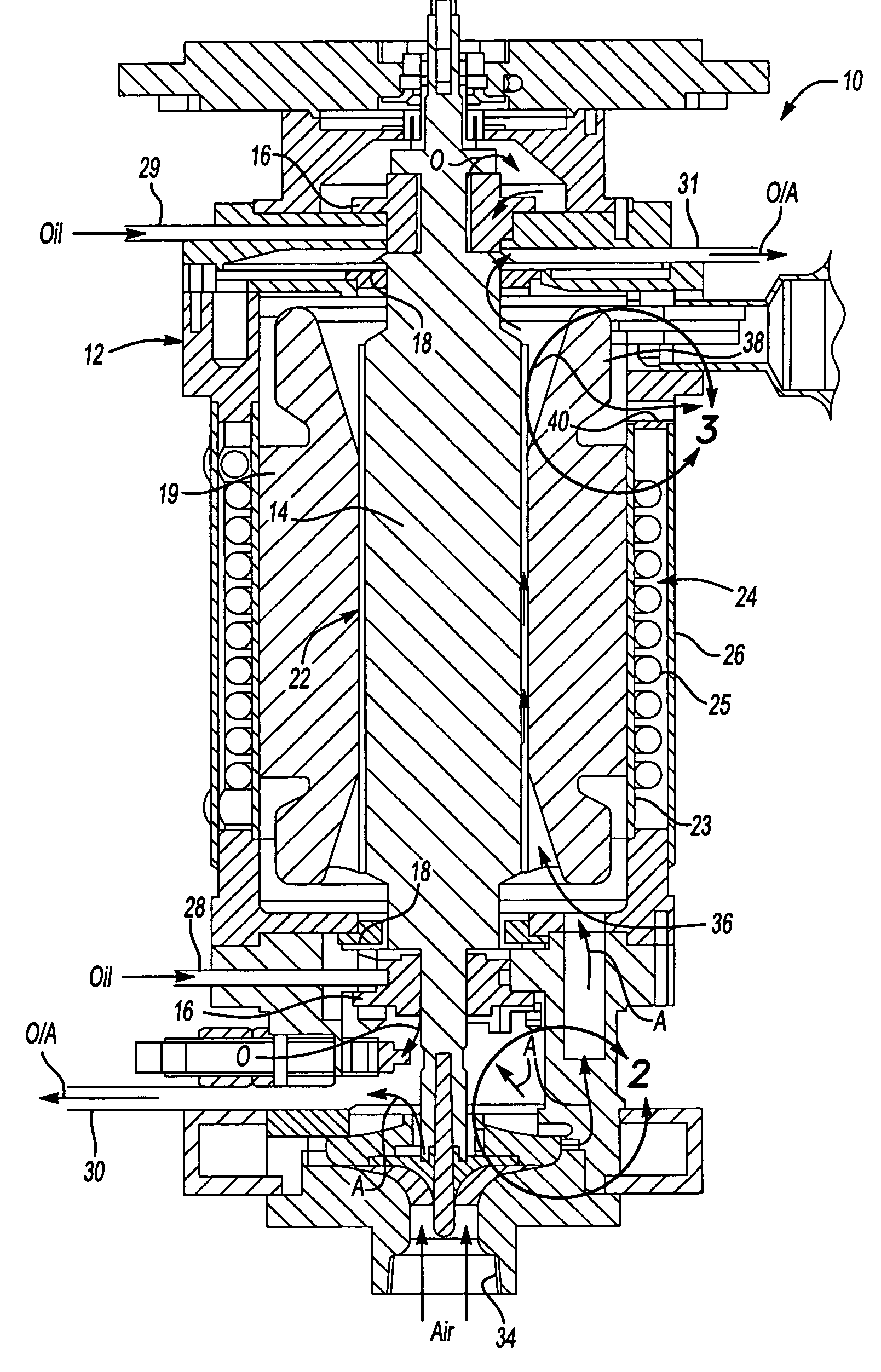
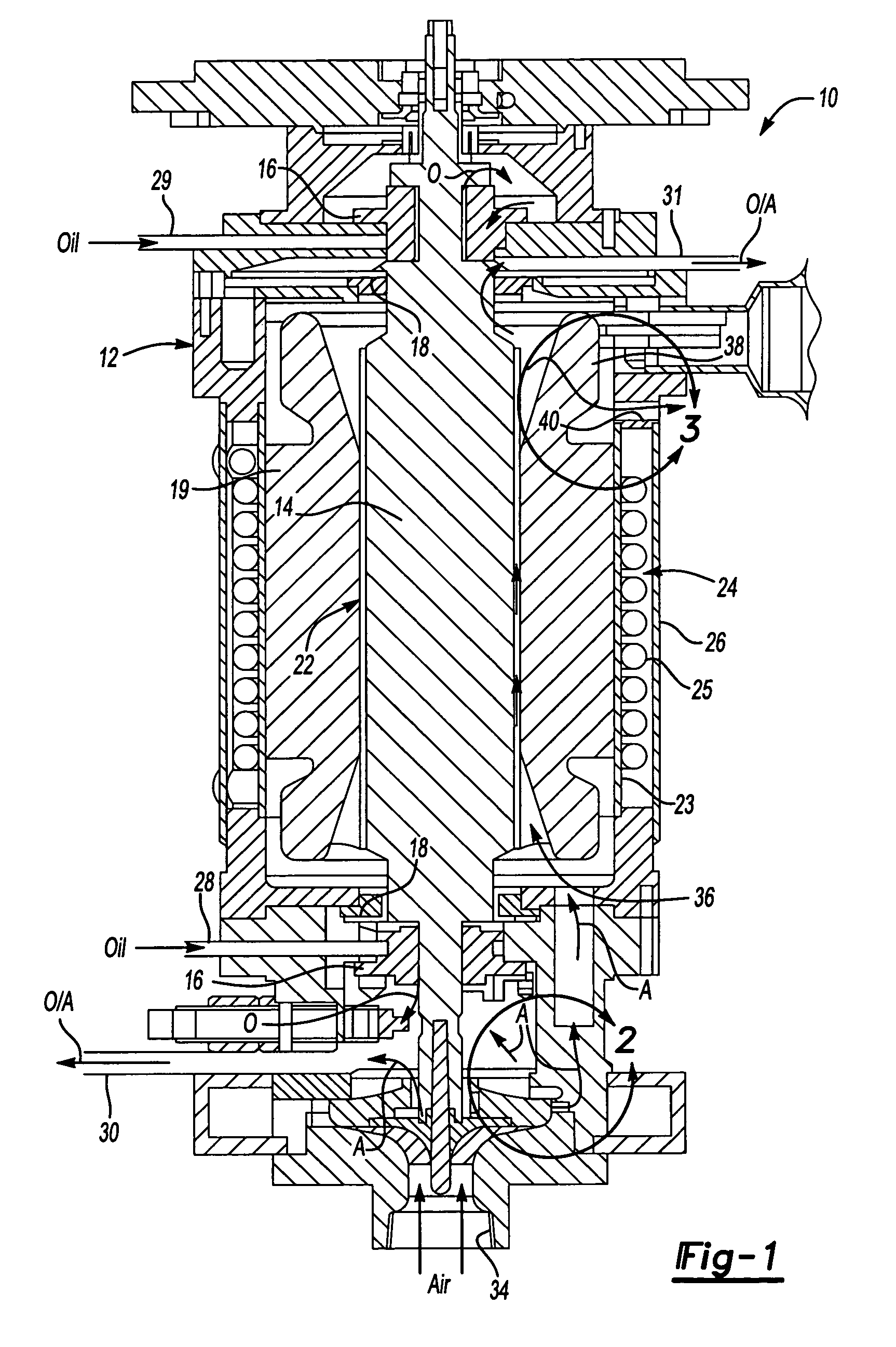
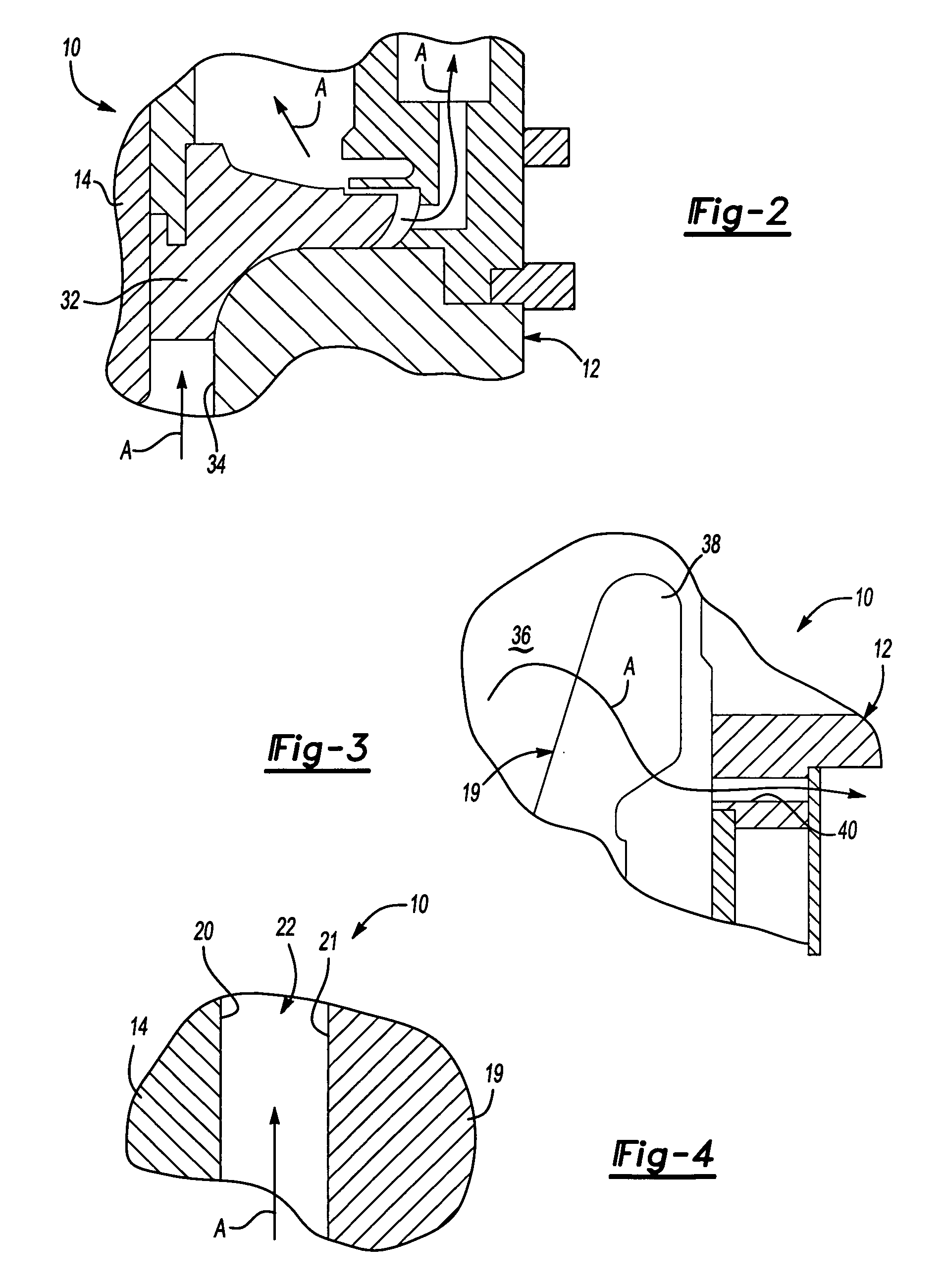
[0014]An electromechanical rotary machine 10 is shown in FIG. 1. The machine 10 includes a housing 12 with a rotor 14 supported within the housing 12 by bearings 16 arranged at either end of the rotor 14. The housing 12 may include one or more components secured to one another. Oil seals 18 are arranged between the housing 12 and rotor 14 and are located further inward of the bearings 16. It should be understood that additional bearings and seals may be used in the machine 10. A stator 19 is disposed within the housing 12 and is arranged about the rotor 14. The machine 10 may be a generator in which case the rotor 14 is driven about its axis to generate an electrical current in the stator 18. Alternatively, the machine 10 may be a motor in which current flows through the stator 19 generating a magnetic field in the rotor 14 to effect rotation of the rotor 14 about its axis.

[0015]The rotor 14 includes an outer surface 20, and the stator 19 includes an inner surface 21 adjacent to the...


PUM


Abstract

A rotary machine cooling system is provided that includes a housing having an inlet and outlet. A rotor supported in the housing for rotation about an axis with the rotor including an outer surface. A stator is disposed within the housing about the rotor having an inner surface adjacent to the outer surface of the rotor. A gap is formed between the inner and outer surfaces sufficient to reduce friction and permit convection cooling. The gap is in fluid communication with the inlet and outlet, and a pumping device pumps a cooling gas from the inlet into the gap and through said outlet. The pumping device includes an impeller affixed to an end portion of the rotor to create an axial airflow into the gap. Preferably, the present invention air cooling system is used in conjunction with a liquid cooling system arranged exteriorly to the stator. The liquid cooling system reduces the amount of air needed to flow between the gap to remove the desired amount of heat from the machine.

Description

BACKGROUND OF THE INVENTION[0001]This invention relates to a cooling system for an electromechanical rotary machine.[0002]Electromechanical rotary machines, such as electric motors or generators, may generate a significant amount of heat during their operation. This is particularly true for electromechanical rotary machines in aircraft applications, which rotate at high speeds of up to 200,000 RPM or more. This heat generation comes from two major sources, electrical losses and friction losses. At very high rotation speeds, friction losses become dominant. These losses cause reduced machine efficiency, and when dissipated in heat, they result in high temperatures. Speeds can be limited by the temperature capabilities of the materials of construction. Successful high-speed motor or generator designs need to minimize the friction losses, not only to improve machine efficiency, but also to provide for carrying the heat of the friction losses away from the surfaces most affected and thu...

Claims


Application Information

Patent Timeline
IPC IPC(8): F04B17/03H02K9/06H02K9/19
CPCH02K9/06H02K2205/12H02K9/19H02K5/20
Inventor MACEYKA, THOMAS D.STROMLEY, JAMES A.
Owner SUNDYNE LLC
Why Eureka
Try Eureka