Vent-blocking inflatable bladder assembly for a HVAC zone control system

a technology of hvac zone control and inflatable bladder, which is applied in the direction of ventilation system, space heating and ventilation details, heating types, etc., can solve the problem that the air tube cannot be removed from the assembly, and achieve the effect of convenient insertion, convenient and fast removal, and improved reliability

Inactive Publication Date: 2010-04-01
EMME E2MS
View PDF4 Cites 36 Cited by
  • Summary
  • Abstract
  • Description
  • Claims
  • Application Information

AI Technical Summary

Benefits of technology

[0012]An object of this invention is to simplify the installation of inflatable bladders used in HVAC zone systems.
[0013]Another object of this invention is to reduce the installation time of inflatable bladders used in HVAC zone systems.
[0014]Another object of this invention is to improve the quality and reliability of installation of inflatable bladders used in HVAC zone systems.
[0015]Another object of this invention is to enable the use of bladder shapes that reduce the volume of air needed to inflate and deflate.SUMMARY
[0016]The invention is an inflatable bladder assembly for use in HVAC zone control systems. The bladder has a nozzle for inflating and deflating the bladder. The nozzle connects to a small air tube that is connected to the control system that provides pressure and vacuum for inflating and deflating the bladder. The bladder has at least two mounting tabs for attaching the bladder to a mounting fixture. A restraint fixture is attached to the mounting fixture. The restraint fixture firmly grips the nozzle and air tube. The restraint fixture allows the nozzle and air tube to be easily inserted into the fixture such that an airtight seal is made between the nozzle and air tube. The restrain fixture strongly resists forces that would remove the nozzle or air tube from the restraint fixture. The mounting fixture is attached to the duct system.
[0017]No tools are required to attach the bladder assembly to the air tube. The air tube is inserted by hand force into the restraint fixture and nozzle. The air tube can not be removed from the assembly by the stresses that occur during installation and operation. This air tube attachment method is easier, faster, and more reliable than prier art. The bladder is securely attached to the mounting fixture so that its orientation is fixed as it is inflated and deflated. This ensures complete sealing or the duct with bladders shapes that use a smaller volume of air for inflation and deflation than prier art.

Problems solved by technology

The air tube can not be removed from the assembly by the stresses that occur during installation and operation.

Method used


Image

  • Vent-blocking inflatable bladder assembly for a HVAC zone control system
  • Vent-blocking inflatable bladder assembly for a HVAC zone control system
  • Vent-blocking inflatable bladder assembly for a HVAC zone control system

Examples


Embodiment Construction

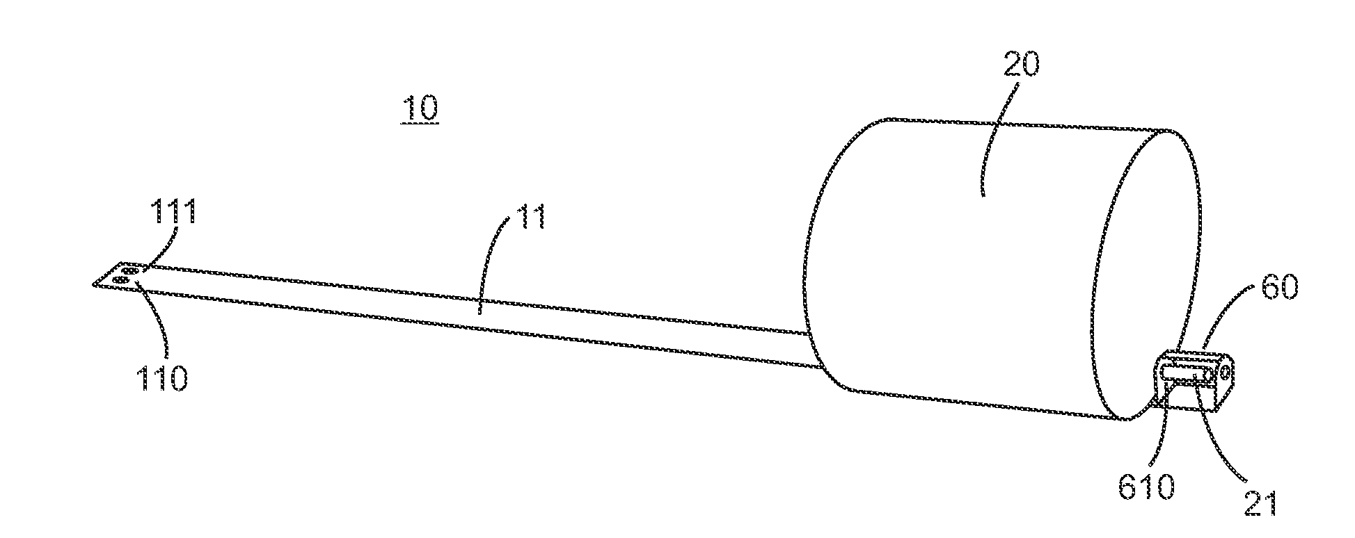
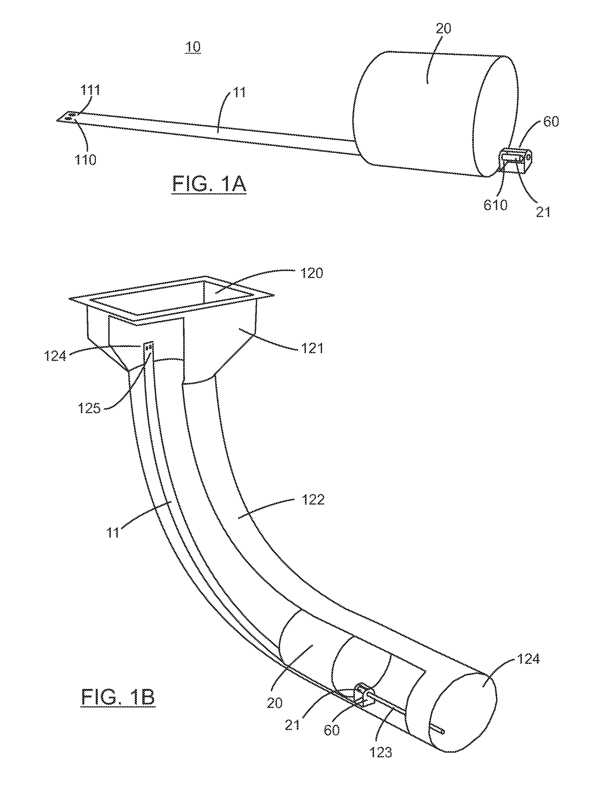
[0040]FIG. 1A shows a typical complete cylindrical bladder assembly 10 as prepared in a factory and supplied for use by an installer of the zone control system. The bladder 20 is made of flexible airtight fabric material. Its shape when inflated is a cylinder. The bladder has a nozzle 21 used to inflate or deflate the bladder. The nozzle is inserted into restraint fixture 60 through hole 610 which firmly grips the outside surface of the nozzle. Each end of the bladder is firmly attached to mounting strap 11. In the preferred embodiment, the strap is typically 1″ wide and 36″ long and made from 20 gauge (approximately 0.035″ thick) mild steel. This should not be taken to limit the scope of the invention since many other materials and dimensions can provide similar function. The requirements are the strap is flexible in one direction perpendicular to its long axis so the strap can easily follow bends in the duct system. The strap is rigid in the direction perpendicular to flexible dir...


PUM


Abstract

The invention is an inflatable bladder assembly for use in HVAC zone control systems. The bladder has a nozzle for inflating and deflating the bladder. The nozzle connects to a small air tube that is connected to the control system that provides pressure and vacuum for inflating and deflating the bladder. The bladder has at least two mounting tabs for attaching the bladder to a mounting fixture. A restraint fixture is attached to the mounting fixture. The restraint fixture firmly grips the nozzle and air tube. The restraint fixture allows the nozzle and air tube to be easily inserted into the fixture such that an airtight seal is made between the nozzle and air tube. The restrain fixture strongly resists forces that would remove the nozzle or air tube from the restraint fixture. The mounting fixture is attached to the duct system.

Description

BACKGROUND OF THE INVENTION[0001]1. Technical Field of the Invention[0002]This invention relates generally to dampers for controllably closing and opening air circulation vents in an HVAC system, and more specifically to an inflatable bladder for insertion inside a vent or a duct.[0003]2. Background Art[0004]Most zone control systems for HVAC systems use electromechanical dampers to selectively control the airflow through portion of the trunk and duct system. Installation of these zone systems requires access to the ducts at multiple locations so that the dampers can be installed. This makes it difficult and expensive to install in existing systems since duct access is restricted, and it is difficult to run control wires form the electromechanical dampers to zone controller.[0005]U.S. Pat. No. 5,348,078 issued Sep. 30, 1994 and U.S. Pat. No. 5,449,319 issued Sep. 12, 1995 to Dushane et. al describe a retrofit room-by-room zone control system for residential forced air HVAC systems t...

Claims


Application Information

Patent Timeline
Patent Type & Authority Applications(United States)
IPC IPC(8): F24F7/00
CPCF24F13/0254F24F13/0218
Inventor ALLES, HAROLD GENE
Owner EMME E2MS
Why Eureka
Try Eureka