
Driving control method and system of fuel cell system

a fuel cell and control method technology, applied in the direction of battery/fuel cell control arrangement, secondary cell servicing/maintenance, electrochemical generators, etc., can solve the problems of fuel cell efficiency decline, poor operation range performance of vehicles, and vehicle performance decline, so as to increase the durability of the fuel cell stack, increase the initial driving performance, and improve the effect of performan

Inactive Publication Date: 2016-01-07
HYUNDAI MOTOR CO LTD +1
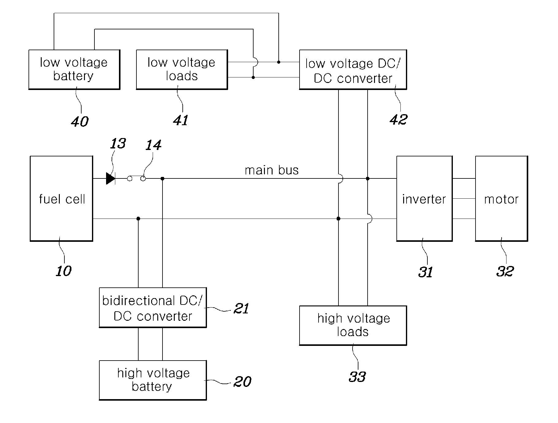
View PDF7 Cites 35 Cited by
  • Summary
  • Abstract
  • Description
  • Claims
  • Application Information

AI Technical Summary

Benefits of technology

The patent text describes a method for driving a fuel cell system that includes various recovery modes to prevent the fuel cell stack from dry-out and to increase its durability. These modes include adjusting coolant temperatures, relieving idle stop conditions, reducing air inflow, decreasing voltage at the main bus terminal, and maintaining a minimum stoichiometry ratio. These modes help to optimize the fuel cell system's performance, minimize performance decrease, and maintain consistent initial driving performance. Overall, the method improves the fuel cell system's reliability and performance through a recovery driving process.

Problems solved by technology

In such a vehicular fuel cell system, when the fuel cell is used as a sole power source for a vehicle it undertakes all loads of the vehicle and, and thus the vehicle shows poor performance in an operation range where the fuel cell decreases in efficiency.
Additionally, in the event of a sudden heavy power load being placed upon the vehicle, the vehicle performance may decrease due to the output power of the fuel cell decreasing rapidly and the driving motor may not be provided with sufficient electric power.
It is well known that a fuel cell may not cope with rapid load variation due to the use of a chemical reaction to generate electricity.
Further, since a fuel cell has unidirectional output, energy introduced from a driving motor upon braking a vehicle may not be recovered, leading to a decrease in the efficiency of a vehicle system.
Since hydrogen crossover has unfavorable effects on fuel-efficiency and durability of a fuel cell, it is necessary to properly regulate anode pressure.

Method used


Image

  • Driving control method and system of fuel cell system
  • Driving control method and system of fuel cell system
  • Driving control method and system of fuel cell system

Examples


Embodiment Construction

[0036]It is understood that the term “vehicle” or “vehicular” or other similar term as used herein is inclusive of motor vehicles in general such as passenger automobiles including sports utility vehicles (SUV), buses, trucks, various commercial vehicles, watercraft including a variety of boats and ships, aircraft, and the like, and includes hybrid vehicles, electric vehicles, plug-in hybrid electric vehicles, hydrogen-powered vehicles and other alternative fuel vehicles (e.g. fuels derived from resources other than petroleum). As referred to herein, a hybrid vehicle is a vehicle that has two or more sources of power, for example both gasoline-powered and electric-powered vehicles.

[0037]It is understood that the exemplary processes may be performed by one or plurality of modules. Additionally, it is understood that the term controller / control unit refers to a hardware device that includes a memory and a processor. The memory is configured to store the modules and the processor is sp...


PUM


Abstract

A driving control system and method of a fuel cell system are provided. The driving control method includes determining, by a controller, when a fuel cell stack is in a water shortage, based on an oversupply of air to the fuel cell stack or a deterioration of the fuel cell stack. A diagnostic level is then assigned to the fuel cell system and at least one recovery driving mode that corresponds to the assigned diagnostic level is performed.

Description

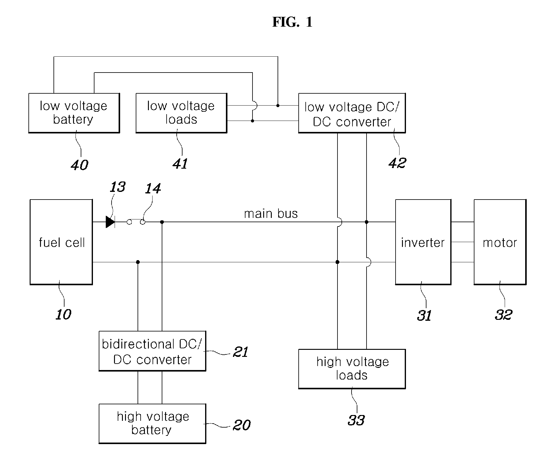
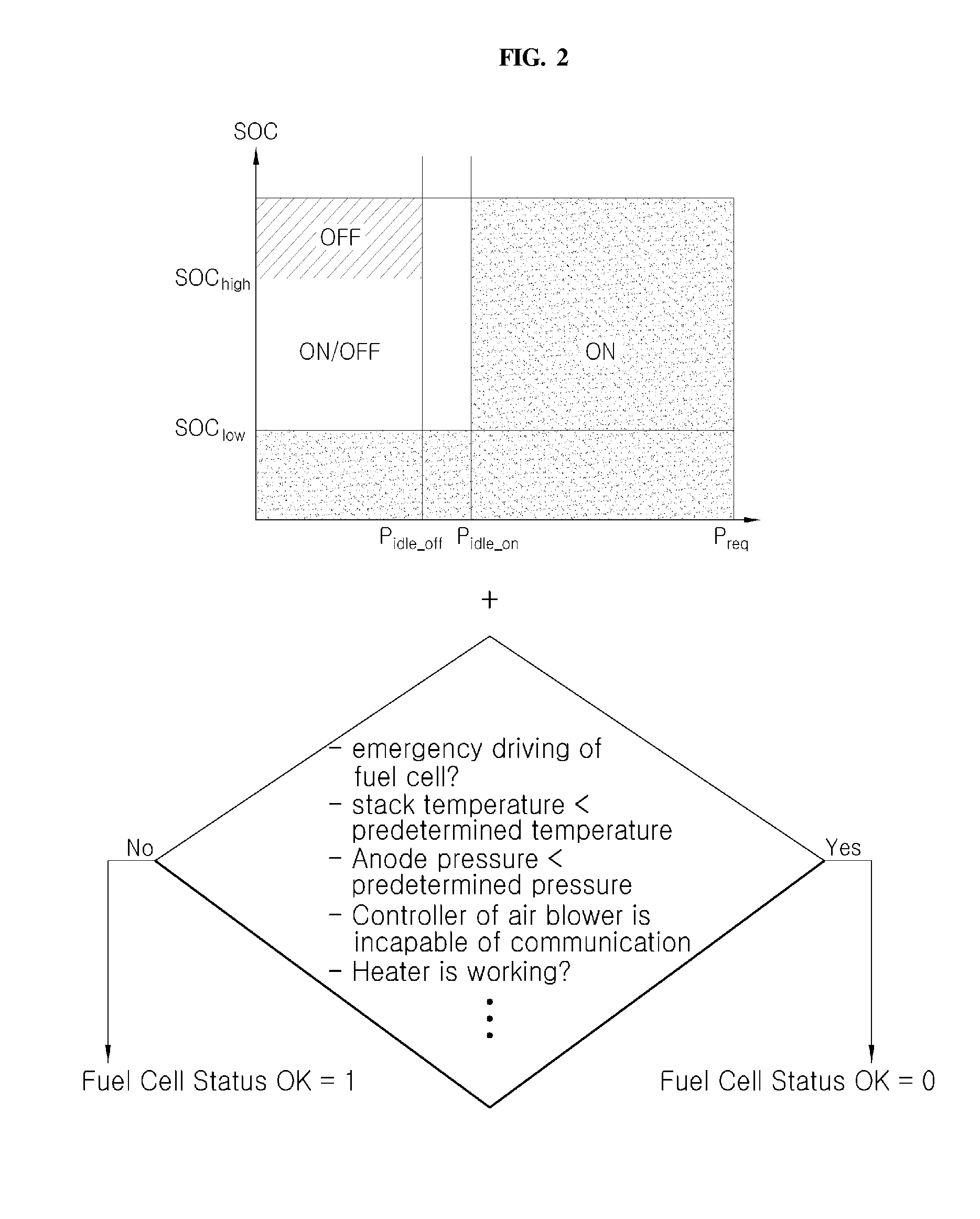
CROSS REFERENCE TO RELATED APPLICATION[0001]The present application claims priority of Korean Patent Application Number 10-2014-0082646 filed on Jul. 2, 2014, the entire contents of which application are incorporated herein for all purposes by this reference.BACKGROUND OF THE INVENTION[0002]1. Field of the Invention[0003]The present invention relates, generally, to a driving control method and system of a fuel cell system and, more particularly, to a fuel cell stack status-based, variable-recovery modality driving control method.[0004]2. Description of the Related Art[0005]A fuel cell system applicable to a hydrogen fuel cell vehicle, a type of eco-friendly vehicle, is composed of a fuel cell stack configured to generate electric power from an electrochemical reaction of reactant gas; a hydrogen supplying system configured to supply hydrogen as fuel to a fuel cell stack; an air supplying system configured to supply gas including oxygen as oxidant in electrochemical reactions; and a ...

Claims


Application Information

Patent Timeline
IPC IPC(8): H01M8/04
CPCH01M8/04291H01M8/04335H01M8/04589H01M8/04522H01M8/04723H01M8/04649H01M8/04559H01M8/04731H01M8/0441H01M10/44H01M2250/20H01M8/04953B60L1/00B60L58/40B60L58/33Y02T90/40Y02T10/70Y02E60/50Y02E60/10H01M8/0444H01M8/04492H01M8/04574H01M8/04895
Inventor KWON, SANG UKJEON, SOON ILKOO, JA HOO
Owner HYUNDAI MOTOR CO LTD
Learn More