Mold for forming disc, method for manufacture same, and mold parts

a technology for discs and molds, applied in the field of disc molds, can solve problems such as slide, and achieve the effects of reducing dimensional variation, improving mold parts wear resistance, and improving disc substrate accuracy

Inactive Publication Date: 2009-03-19
SUMITOMO HEAVY IND LTD +1
View PDF3 Cites 2 Cited by
  • Summary
  • Abstract
  • Description
  • Claims
  • Application Information

AI Technical Summary

Benefits of technology

[0011]A sliding surface of a mold part disposed on one of the first and second molds is treated by means of low-temperature nitriding.
[0012]According to the present invention, a disc-molding mold comprises a first mold including a first support plate and a first mirror-surface disc attached to the first support plate; and a second mold including a second support plate and a second mirror-surface disc attached to the second support plate.
[0014]In this case, since the mold part is treated by means of low-temperature nitriding, the wear resistance of the mold part can be improved. In addition, since the treatment temperature is low, even when low-temperature nitriding is performed on a mold part which is complicated in shape, the mold part does not deform, and its dimensional variation can be decreased. As a result, accuracy of disc substrates can be improved.

Problems solved by technology

Incidentally, each time molding is performed, the cavity ring comes into contact with a butt ring provided on the stationary-side mold assembly and is caused to slide.

Method used


Image

  • Mold for forming disc, method for manufacture same, and mold parts
  • Mold for forming disc, method for manufacture same, and mold parts
  • Mold for forming disc, method for manufacture same, and mold parts

Examples


Embodiment Construction

[0024]An embodiment of the present invention will next be described in detail with reference to the drawings. Notably, in this case, an injection molding machine, which is an example molding machine, will be described.

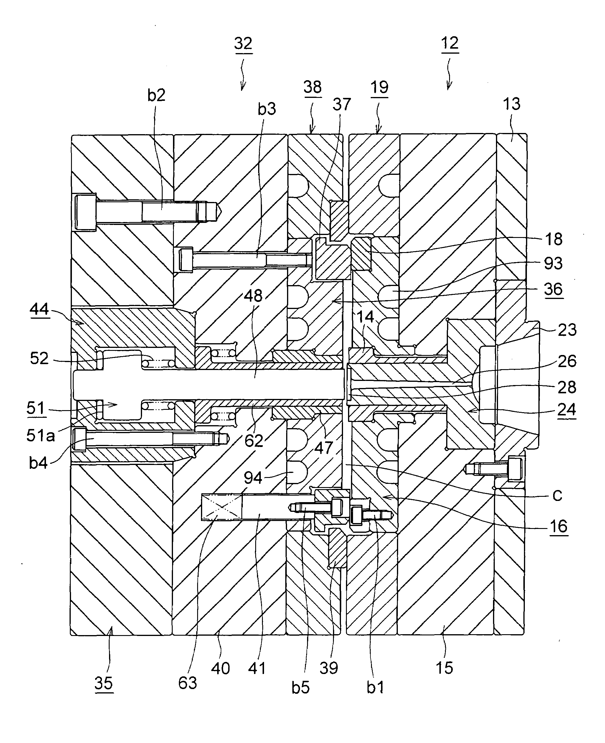
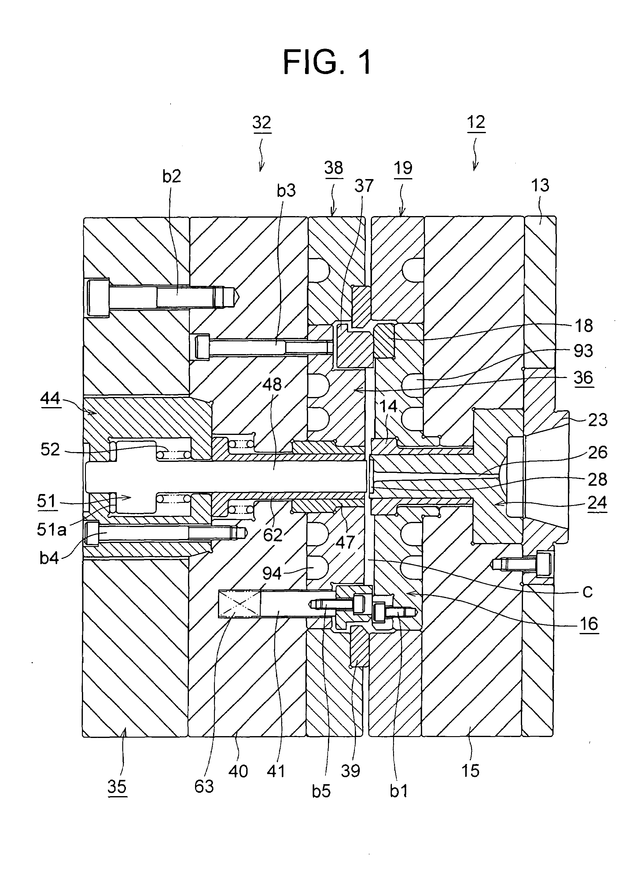
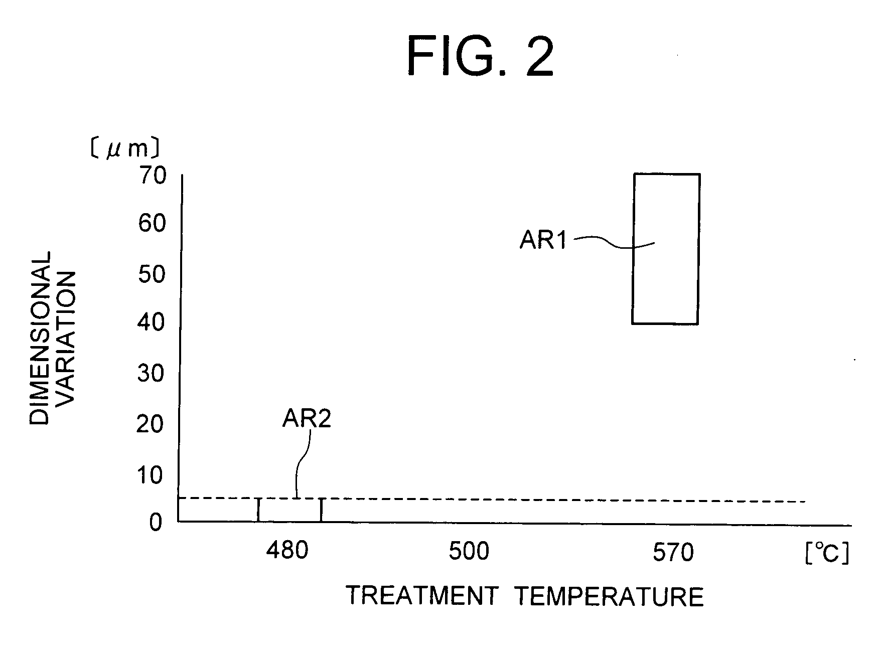
[0025]FIG. 1 is a sectional view of a disc-molding mold according to the embodiment of the present invention. FIG. 2 is a graph showing the relation between treatment temperature and dimensional variation of a cavity ring in the embodiment of the present invention. In FIG. 2, the horizontal axis represents treatment temperature, and the vertical axis represents dimensional variation.

[0026]In these drawings, reference numeral 12 denotes a stationary-side mold assembly (first mold) attached to an unillustrated stationary platen via an attachment plate 13. The mold assembly 12 includes a base plate (first support plate) 15; a disc plate (first mirror-surface disc) 16 attached to the base plate 15; a locating ring 23 disposed within in the attachment plate 13 in such a man...


PUM

PropertyMeasurementUnit
temperatureaaaaaaaaaa

Abstract

An object is to improve the wear resistance of a mold part and improve accuracy of disc substrates. A disc-molding mold comprises a first mold including a first support plate and a first mirror-surface disc attached to the first support plate; and a second mold including a second support plate and a second mirror-surface disc attached to the second support plate. A sliding surface of a mold part disposed on one of the first and second molds is treated by means of low-temperature nitriding. In this case, since the mold part is treated by means of low-temperature nitriding, the wear resistance of the mold part can be improved. In addition, since the treatment temperature is low, even when low-temperature nitriding is performed on a mold part which is complicated in shape, the mold part does not deform, and its dimensional variation can be decreased.

Description

TECHNICAL FIELD[0001]The present invention relates to a disc-molding mold, a method for manufacturing the same, and a mold part.BACKGROUND ART[0002]Conventionally, in a molding machine, such as an injection molding machine for molding disc substrates, resin melted within a heating cylinder is charged into a cavity in a disc-molding mold, and is then cooled and solidified in the cavity so as to obtain a disc substrate.[0003]For such a molding process, the above-mentioned injection molding machine includes the disc-molding mold consisting of a stationary-side mold assembly and a movable-side mold assembly; an injection apparatus for charging resin into a cavity; and a mold-clamping apparatus for bringing the movable-side mold assembly into contact with the stationary-side mold assembly and separating the movable-side mold assembly from the stationary-side mold assembly. The mold-clamping apparatus is operated so as to advance and retract the movable-side mold assembly to thereby close...

Claims


Application Information

Patent Timeline
Patent Type & Authority Applications(United States)
IPC IPC(8): B29C45/26
CPCB29C33/56G11B7/263B29C45/263B29C45/26B29C33/38B29L2017/00G11B7/26
Inventor GOTO, YOSHIYUKISHIBUTANI, YUJIINADA, YUICHI
Owner SUMITOMO HEAVY IND LTD
Why Eureka
Try Eureka