
Intervertebral Disc Reamer

Active Publication Date: 2009-03-19
SPINAL ELEMENTS INC
View PDF9 Cites 42 Cited by
  • Summary
  • Abstract
  • Description
  • Claims
  • Application Information

AI Technical Summary

Benefits of technology

[0006]An intervertebral disc reamer includes various design versions for different approaches of disc surgery, including but not limited to arthroscopic disc excision and endplate preparation, transforaminal disc excision and endplate preparation, posterior lumbar interbody procedures, transverse lumbar interbody procedures, anterior interbody techniques, and the like. Safety of the device during surgery is ensured by preventing the operation of the disc reamer outside of the disc space by utilizing threaded cannulas that are locked into the vertebral endplates and by use of a flexible guide wire that controls the direction and depth of reaming under fluoroscopic control.
[0008]In one arrangement, the reamer head is attached to the flexible shaft via a neck that has a narrow cross-section so as to facilitate flexibility of articulation.

Problems solved by technology

Meticulous disc space preparation is required for either fusion or disc replacement, and this task is invariably laborious and is often performed sub-optimally.
While it is possible to remove the endplates in a reproducible fashion through the open anterior approach, it is difficult to quantify the completeness of the disc excision through the posterior and transforaminal approaches.
At this time there is no effective way of thoroughly excising the disc and preparing the end-plate through the least invasive approaches, such as the arthroscopic approach, for disc replacement or fusion.

Method used


Image

  • Intervertebral Disc Reamer
  • Intervertebral Disc Reamer
  • Intervertebral Disc Reamer

Examples


Embodiment Construction

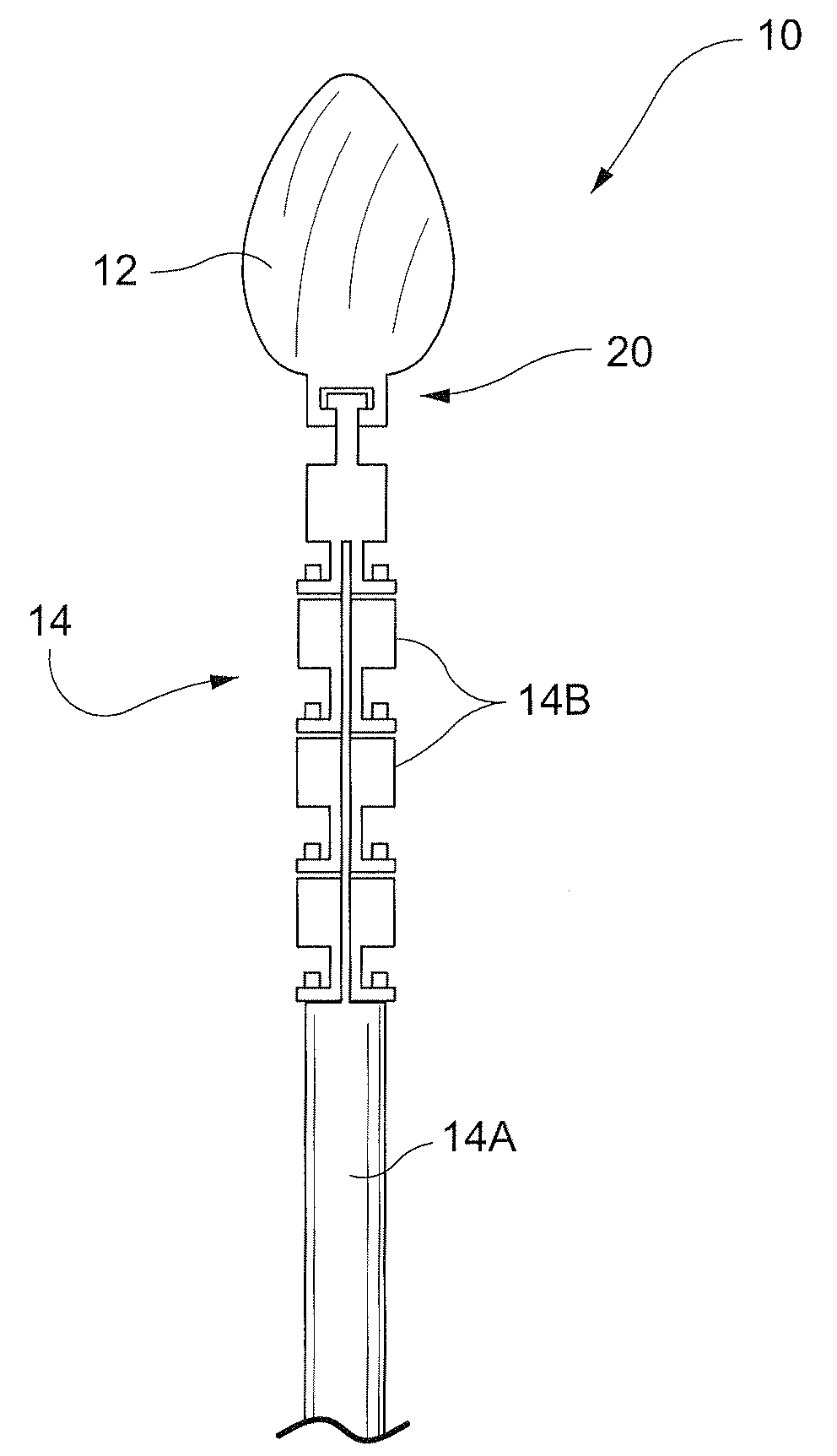
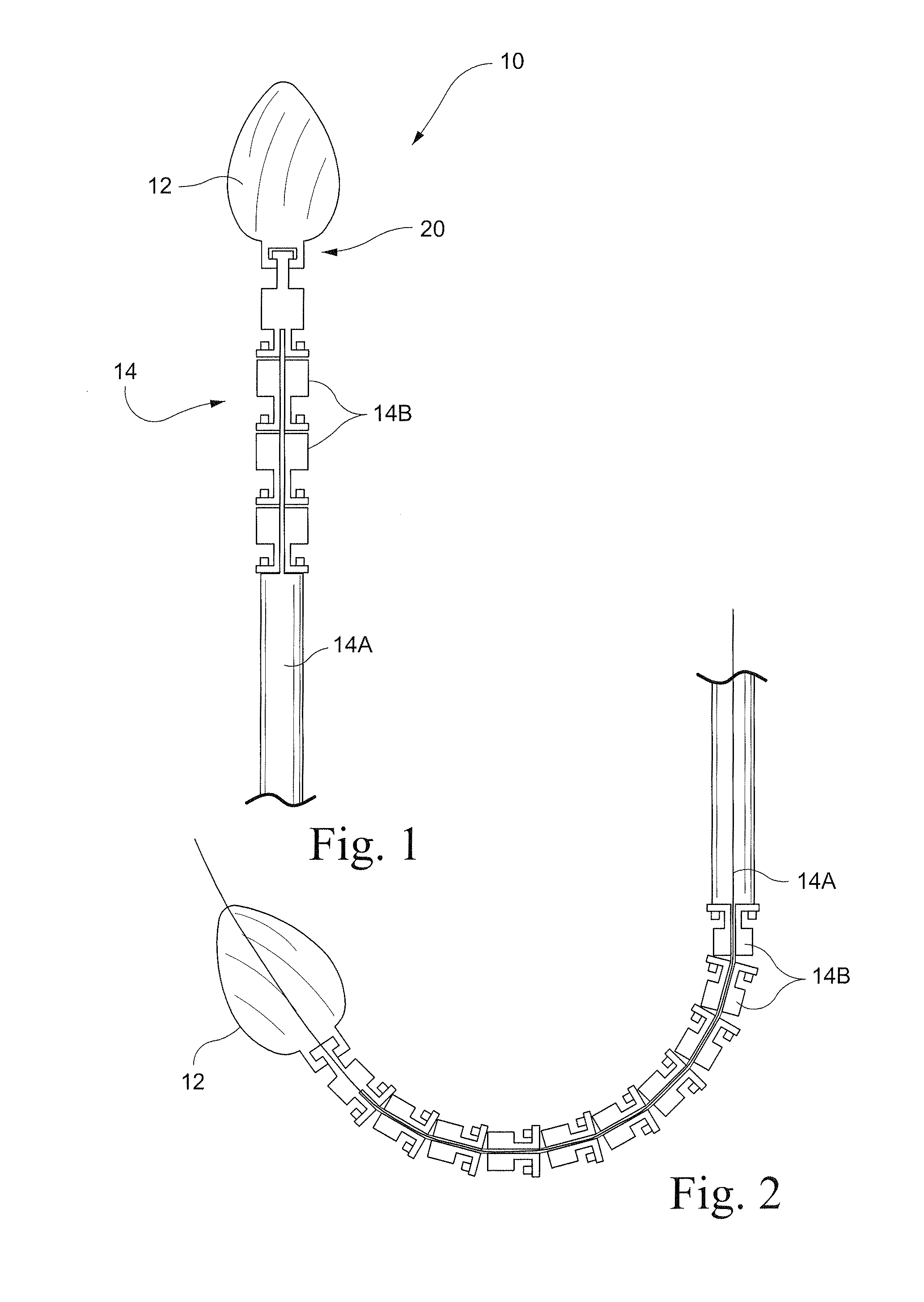
[0029]Various embodiments of the intervertebral disc reamer will be described with reference to the drawings, where like elements are represented by like reference numerals. FIGS. 1 and 2 show an exemplary intervertebral disc reamer 10 of a preferred construction. Generally, the disc reamer 10 may be formed of a one-piece reamer head 12 with a shaft 14 such as a fixed but flexible shaft or a chain of shaft links 14B that are interlinked and movable relative to each other to impart flexibility, and a proximal shaft 14A.

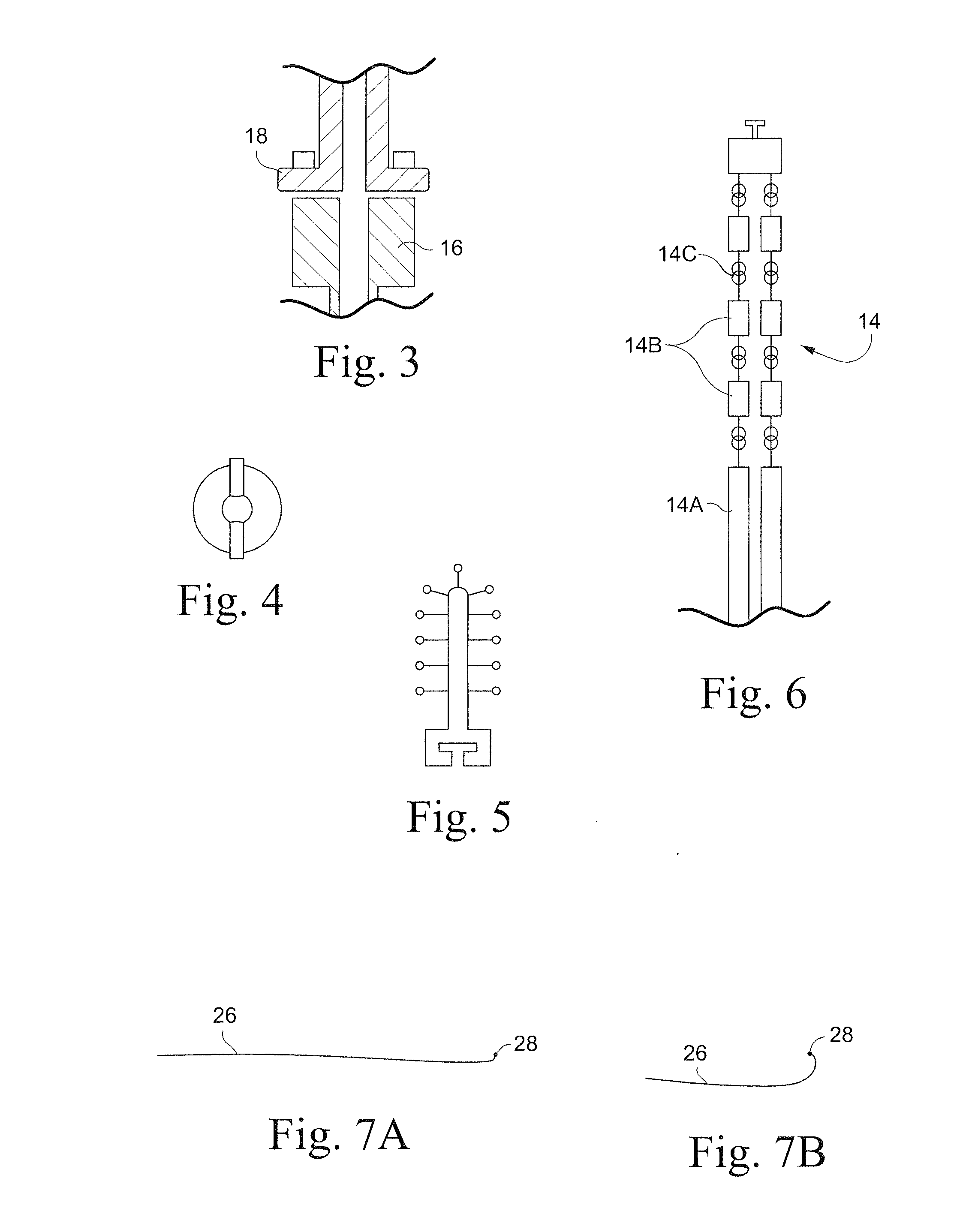
[0030]The reamer device 10 may be formed using different materials, including various metal alloys, plastic materials and the like. Generally, each of the shaft links 14B includes a link body 16 (FIG. 3), which is the female part of the piece into which the male part 18 of the articulating neighbor fits. The body 16 of the shaft links 14B is preferably oriented proximal but may be distal. A neck 20 is preferably attached to the distal part of the body 16 (at least adja...


PUM


Abstract

An intervertebral disc reamer includes a flexible shaft having a shaft channel, and a reamer head attached to the flexible shaft and movable relative to the flexible shaft. The reamer head has a reamer channel. The shaft channel and the reamer channel are aligned to define a continuous guide wire channel for the disc reamer. The disc reamer addresses the quality of disc removal and endplate preparation, minimizes the trauma of surgery, minimizes blood loss, and markedly reduces surgical time.

Description

CROSS-REFERENCES TO RELATED APPLICATIONS[0001]This application claims the benefit of U.S. Provisional Patent Application Ser. No. 60 / 972,412, filed Sep. 14, 2007, the entire content of which is herein incorporated by reference.STATEMENT REGARDING FEDERALLY SPONSORED RESEARCH OR DEVELOPMENT[0002](Not Applicable)BACKGROUND OF THE INVENTION[0003]Thousands of spine procedures are performed daily in the United States and around the world. Many of these procedures involve removal of the disc material in preparation for either fusion or replacement of the disc. Meticulous disc space preparation is required for either fusion or disc replacement, and this task is invariably laborious and is often performed sub-optimally.[0004]The variety of disc surgical procedures is rapidly increasing, keeping abreast with the progress of technology. Disc excision usually involves removal of the extruded nucleus material as well as the nuclear material lying loosely in the disc space. Partial disc replacem...

Claims


Application Information

Patent Timeline
IPC IPC(8): A61B17/00A61B17/32
CPCA61B17/1671A61B17/32002A61B2017/320032A61B2017/1602A61B2017/22038A61B2017/00261
Inventor OSMAN, SAID G.
Owner SPINAL ELEMENTS INC
Learn More