Stent Design Allowing Extended Release of Drug and/or Enhanced Adhesion of Polymer to OD Surface

Inactive Publication Date: 2009-03-19
BOSTON SCI SCIMED INC
View PDF55 Cites 42 Cited by
  • Summary
  • Abstract
  • Description
  • Claims
  • Application Information

AI Technical Summary

Benefits of technology

[0015]The invention is also directed to methods of engaging a therapeutic

Problems solved by technology

Many prior art stents however are not wholly satisfactory for use where the site of desired application of the stent is juxtaposed or extends

Method used


Image

  • Stent Design Allowing Extended Release of Drug and/or Enhanced Adhesion of Polymer to OD Surface
  • Stent Design Allowing Extended Release of Drug and/or Enhanced Adhesion of Polymer to OD Surface
  • Stent Design Allowing Extended Release of Drug and/or Enhanced Adhesion of Polymer to OD Surface

Examples


Embodiment Construction

[0066]While this invention may be embodied in many different forms, there are described in detail herein specific embodiments of the invention. This description is an exemplification of the principles of the invention and is not intended to limit the invention to the particular embodiments illustrated.

[0067]For the purposes of this disclosure, like reference numerals in the figures shall refer to like features unless otherwise indicated.

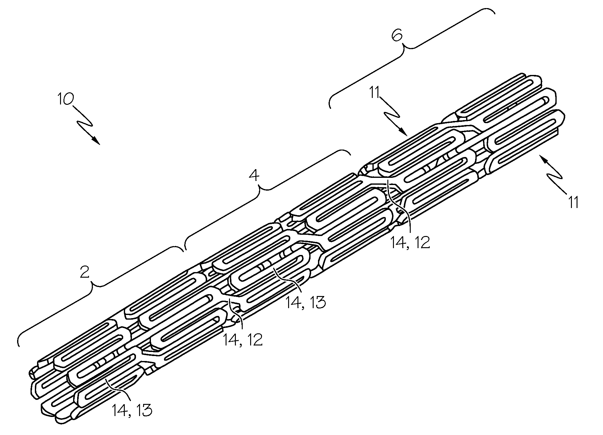
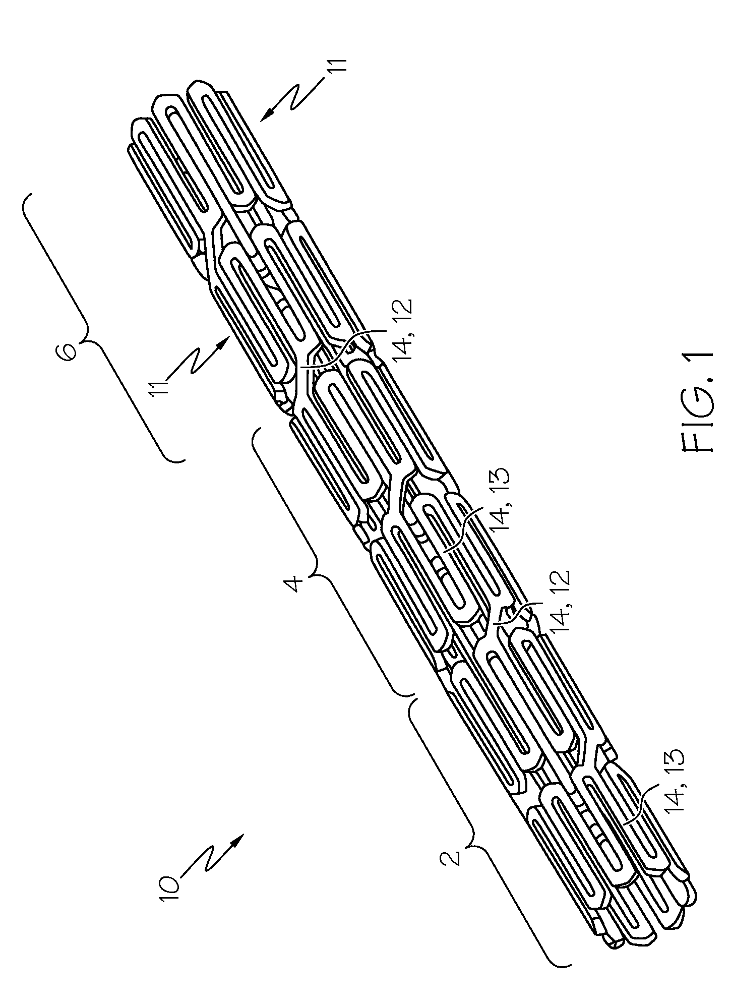
[0068]FIG. 1 depicts a stent 10 comprising a plurality of members 14 that form circumferential rings 11 that extend about the circumference of the stent 10. The stent 10 illustrated in FIG. 1 is an example of a configuration for a non-bifurcated stent 10. The stent 10 configuration in FIG. 1 is presented only as an example of one stent 10 configuration that can be used to deliver therapeutic regimens, any stent 10 configuration can be used, including configurations for bifurcated stents 10. Stents 10 have different regions and / or subregions. As a non...


PUM


Abstract

The invention is directed to mechanisms and methods that reduce the delamination of a therapeutic agent from a stent. The mechanisms include holes (channels, wells, and other hole configurations), protrusions, sintered metal cores, clamps/staples, pins, and stainless steel shields.

Description

CROSS-REFERENCE TO RELATED APPLICATIONS[0001]Not ApplicableSTATEMENT REGARDING FEDERALLY SPONSORED RESEARCH[0002]Not ApplicableBACKGROUND OF THE INVENTION[0003]1. Field of the Invention[0004]In some embodiments this invention relates to implantable medical devices, their manufacture, and methods of use. Some embodiments are directed to delivery systems, such as catheter systems of all types, which are utilized in the delivery of such devices.[0005]2. Description of the Related Art[0006]A stent is a medical device introduced to a body lumen and is well known in the art. Typically, a stent is implanted in a blood vessel at the site of a stenosis or aneurysm endoluminally, i.e. by so-called “minimally invasive techniques” in which the stent in a radially reduced configuration, optionally restrained in a radially compressed configuration by a sheath and / or catheter, is delivered by a stent delivery system or “introducer” to the site where it is required. The introducer may enter the bod...

Claims


Application Information

Patent Timeline
IPC IPC(8): A61F2/82
CPCA61F2/91A61F2250/0067A61F2220/0083A61F2210/0076A61F2220/0066A61F2250/0068
Inventor GIRTON, TIMOTHY S.LINDQUIST, JEFFREY S.KNAPP, DAVID M.HEIDNER, MATTGREGORICH, DANIELANAND, UMANGEDELMAN, PETERMILLER, MATTHEW J.RIZQ, RAEDWEBER, JANEIDENSCHINK, TRACEECHEN, JOHN J.KOKATE, JAYKEEP Y.BHAVE, APARNAHARRISON, KENT D.KVEEN, GRAIG L.ARCAND, BENJAMINKUEHLING, MICHAEL
Owner BOSTON SCI SCIMED INC
Why Eureka
Try Eureka