Multi-use personal ventilation/filtration system

a ventilation/filtration system and multi-use technology, applied in the direction of machines/engines, liquid fuel engine components, circumferential flow pumps, etc., can solve the problems of reduced productivity at work, poor air quality, and many people's discomfor

Inactive Publication Date: 2009-03-26
PROPULSIVE WING
View PDF9 Cites 72 Cited by
  • Summary
  • Abstract
  • Description
  • Claims
  • Application Information

AI Technical Summary

Benefits of technology

[0010]A personal ventilation system uses a cross-flow fan and one or more filters, where the filter preferably has a cylindrical or elongated elliptical shape that at least partially surrounds the rotor of the cross-flow fan. The filters preferably remove particles, undesired gases, and micro-organisms.

Problems solved by technology

Allergens and other contaminants (e.g. pollen, mold, car exhaust, and smoke) in public places cause discomfort for many people.
It is well established that poor quality of breathed air in the workplace results in reduced productivity at work.
Air quality is also poor on airplanes, and travelers are often exposed to diseases from other passengers.
Mold and toxins from cleaning products found in schools often cause problems with children, resulting in unhealthy learning environments due to heightened allergic sensitivity.
Conventional air purification devices perform well to reduce the ambient levels of contaminants in a room; however, they fail to adequately filter the air as it travels from the floor to the mouth.
As a result, significant contaminants, both particulate and gaseous, have an opportunity to enter the airstream in this region, greatly reducing the perceived effect of the room air purifier.
There remains a gap in filtration systems when considering the needs of the individual, especially in terms of the personal environment.
Large, bulky, floor models are effective in general removal of pollutants from a room; however, they tend to be noisy, expensive, and consume large amounts of power.
At the other end of the spectrum, those that are wearable (i.e. the true personal ventilation unit for the individual), do not work well, and many release ozone as a bi-product of the filtration process, which is then breathed in by the user.

Method used


Image

  • Multi-use personal ventilation/filtration system
  • Multi-use personal ventilation/filtration system
  • Multi-use personal ventilation/filtration system

Examples


Embodiment Construction

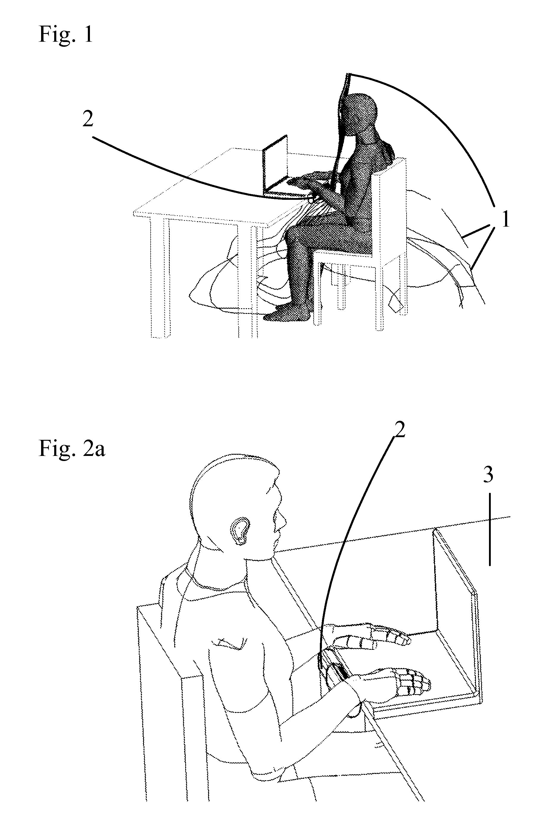
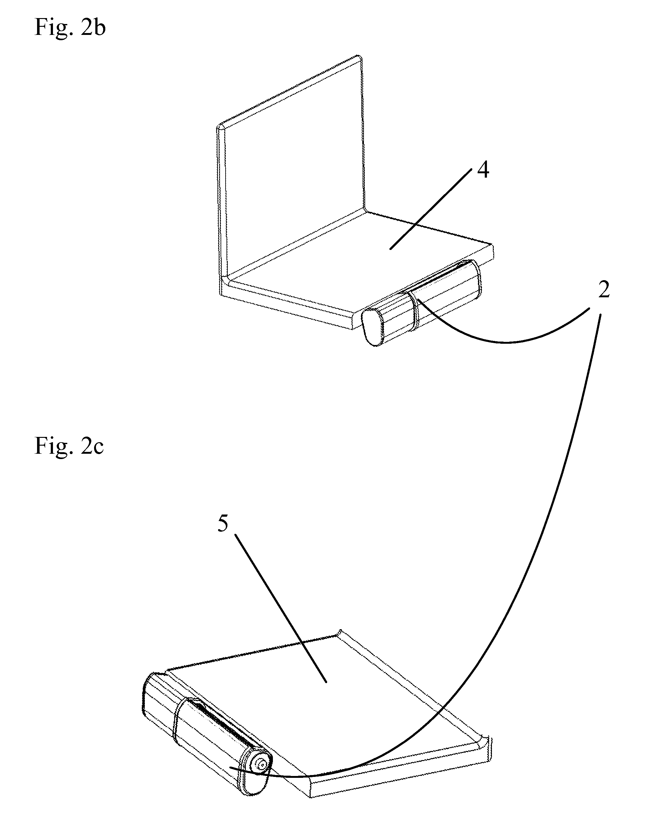
[0030]The invention is a compact, quiet, low power personal ventilation system capable of delivering filtered air to the user. A personal device, as defined herein, is a device that ventilates air for human or animal consumption.

[0031]A fan, as defined herein, is a device that accelerates air movement using impellers or blades rotating around an axis thereby directing air at an increased pressure.

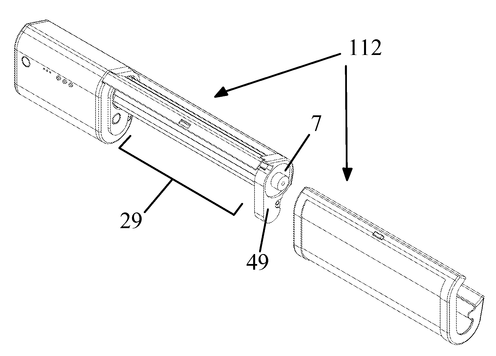
[0032]Results from an unsteady 2D CFD simulation are shown in FIG. 3, and clearly show the radial path the flow takes. The ventilation device preferably uses a cross-flow fan, as shown in FIG. 4a. A 2-stage machine, the flow passes through the blades twice at 120 and 122, resulting in both high flow rate and a rise in pressure. By utilizing a “water-bottle” shaped blower unit, the shape of the fan and flow path create a compact, efficient device for personal ventilation use.

[0033]Solidworks CAD and Starccm+CFD software packages were used to simulate the personal ventilation device. In parti...


PUM

PropertyMeasurementUnit
velocityaaaaaaaaaa
velocityaaaaaaaaaa
exhaust angleaaaaaaaaaa

Abstract

A personal ventilation system uses a cross-flow fan and one or more filters, where the filter preferably has a cylindrical or elongated elliptical shape that at least partially surrounds the rotor of the cross-flow fan. The filters preferably remove particles, undesired gases, and micro-organisms.

Description

REFERENCE TO RELATED APPLICATIONS[0001]This application claims one or more inventions which were disclosed in Provisional Application No. 60 / 975,377, filed Sep. 26, 2007, entitled “Multi-Use Personal Ventilation / Filtration System”. The benefit under 35 USC §119(e) of the United States provisional application is hereby claimed, and the aforementioned application is hereby incorporated herein by reference.BACKGROUND OF THE INVENTION[0002]1. Field of the Invention[0003]The invention pertains to the field of ventilation systems. More particularly, the invention pertains to ventilation and filtration systems for personal use.[0004]2. Description of Related Art[0005]Allergens and other contaminants (e.g. pollen, mold, car exhaust, and smoke) in public places cause discomfort for many people. It is well established that poor quality of breathed air in the workplace results in reduced productivity at work. Air quality is also poor on airplanes, and travelers are often exposed to diseases fr...

Claims


Application Information

Patent Timeline
Patent Type & Authority Applications(United States)
IPC IPC(8): B01D46/42H05K7/20B01D46/00B01D50/00F04D5/00
CPCB01D46/42
Inventor KUMMER, JOSEPHALLRED, JIMMIE B.
Owner PROPULSIVE WING
Why Eureka
Try Eureka