Economical Polar-Axis Solar Tracker for a Circular Reflective Dish

a solar tracker and reflective dish technology, applied in the field of solar energy, can solve the problems of large torque required to properly orient such a tracker, simplistic tracking schemes that could easily be confused to the point of no longer working, and large torques

Inactive Publication Date: 2009-03-26
XEROX CORP
View PDF8 Cites 12 Cited by
  • Summary
  • Abstract
  • Description
  • Claims
  • Application Information

AI Technical Summary

Problems solved by technology

Note that the dish in FIG. 1a is high above the ground, which is a distinct disadvantage during windstorms.
A further disadvantage is that the torques required to properly orient such a tracker are significant, since the full weight of the dish plus the solar energy receiver must be lifted in order to aim the tracker properly. FIG. 1b shows an az / el tracker which has its dish somewhat lower to the ground.
One distinct disadvantage of az-el trackers is that difficulties arise when they are installed in tropical locations, that is, anywhere between the tropic of capricorn and the tropic of cancer; a huge belt around the planet from 23.5 degrees south to 23.5 degrees north.
Simplistic tracking schemes could easily be confused to the point of no longer working when confronted with such an extreme discontinuity.
The tracker in FIG. 2a (from U.S. Pat. No. 6,284,968, granted Sep. 4, 2001) has many of the disadvantages of the tracker in FIG. 1a: the dish is high above the ground, and large torques are required in order to track the sun.
The shared motor concept has the potential to reduce costs, but that potential is not fully realized in this case.
The imbalanced weight of the dishes would require large torques in order to track the sun, as mentioned with prior trackers.
When the system of imbalanced dishes are connected together, the torques accumulate rather than canceling each other out, so that a drive motor handling four dishes must be at least four times as powerful as the single motor was, and thus significantly more expensive.
Another drawback of this design is the cumulative backlash that will be involved in the system of all of bevel gears.
Since there are four such junctions between the control motors and the dishes, that play will be quadrupled, significantly lowering the precision of the tracking.
The only disadvantage of this excellent design is that the dishes are highly exposed to winds, especially the dishes which are concentrating light onto the upper side of the boilers.
This problem, which is relatively minor near Delhi, becomes progressively worse at higher latitudes, because the entire assembly must be rotated to stay in parallel with the earth's rotational axis, which at higher latitudes will put the upper dish higher and higher above the ground.

Method used


Image

  • Economical Polar-Axis Solar Tracker for a Circular Reflective Dish
  • Economical Polar-Axis Solar Tracker for a Circular Reflective Dish
  • Economical Polar-Axis Solar Tracker for a Circular Reflective Dish

Examples


Embodiment Construction

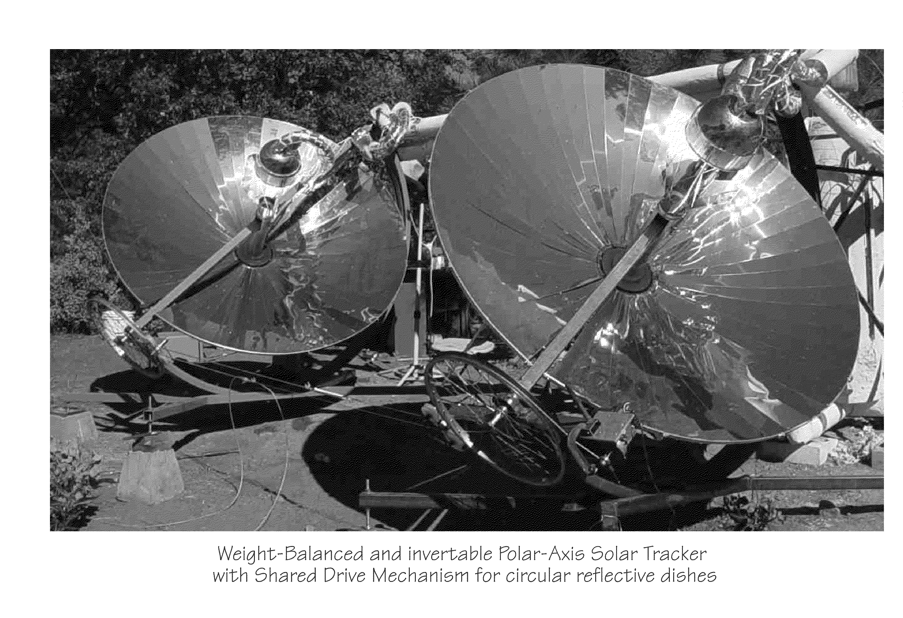
[0028]In FIGS. 3a and 3b, a working prototype of one embodiment of this invention is shown photographically from two different views. While this prototype has been useful in proving the essential concepts of this invention to be valid and workable, the preferred embodiment is described in the following text and figures, and not in these photographs. The photographs are provided because they help the reader to better visualize the 3-dimensional structure and shape of the preferred embodiment, which may be harder to grasp from the 2-dimensional drawings.

[0029]The fundamental details of the preferred embodiment are shown schematically in FIG. 4. Support base 401 provides a stable platform for the tracker, the long axis of which should be accurately aligned in a true north-south direction. FIG. 4 is drawn for a tracker at 28.46 degrees latitude, which would be appropriate for an installation near New Delhi, India. FIG. 4 shows a West-looking view of that tracker, so that rightward on th...


PUM


Abstract

The most urgent need in the field of solar energy is to lower the final cost per watt of all involved components. Some of the most expensive components within a solar tracker go into the precision drive system which accurately follows the motion of the sun. This invention reduces the complexity and the required number of drive components in a tracker optimized for reflective dishes. With this invention a single drive motor can keep 20 or more large reflective dishes accurately tracking the sun, whereas 40 drive motors with more complex control systems would typically be required for the same number of dishes. In addition this invention allows for complete inversion of the dishes, which helps reduce dust accumulation on the optical surfaces and lowers wind resistance during storms.

Description

PRIORITY CLAIM[0001]This application is a continuation-in-part of Indian patent application No. 2010 / DEL / 2007 filed on Sep. 24, 2007 and entitled “An Economical Solar Tracker for a Concentrating Reflective Dish”.FIELD OF THE INVENTION[0002]The invention relates to solar energy, and more specifically to methods for tracking the motion of the sun as it moves through the sky, enabling more efficient concentration and utilization of the energy coming from the sun.BACKGROUND OF THE INVENTION[0003]In order to accurately track the motion of the sun through the sky, it's necessary to somehow replicate that motion. The majority of solar trackers deal with the sun's motion as if it were an arbitrary series of azimuth-elevation (az-el) coordinates. They generally depend on complex computer software to predict those coordinates, and / or a sophisticated, closed-loop, two-axis control system to move the tracker so that it accurately follows the motion of the sun. Such solar trackers are called az-...

Claims


Application Information

Patent Timeline
Patent Type & Authority Applications(United States)
IPC IPC(8): F24J2/38F24S50/20
CPCF24J2/12F24J2/5427F24J2002/5286F24J2002/5458Y02E10/47F24J2002/5472F24J2002/5493Y02E10/42F24J2002/5468F24S23/71F24S2025/017F24S2030/133F24S30/458F24S2030/137F24S2030/18F24S2030/136Y02E10/40
Inventor BROWN, DANIEL NORVIN
Owner XEROX CORP
Why Eureka
Try Eureka