Optical fiber for an optical fiber laser, method for fabricating the same, and optical fiber laser

Inactive Publication Date: 2009-03-26
HITACHI CABLE
View PDF4 Cites 33 Cited by
  • Summary
  • Abstract
  • Description
  • Claims
  • Application Information

AI Technical Summary

Benefits of technology

[0035]According to the present invention, it is possible to easily control an optical absorption characteristic of the exciting light along a

Problems solved by technology

Accordingly, in the conventional optical fiber 91, there is a disadvantage in that a temperature of the optical fiber 91 is increased in accordance with an increase in the output power of the optical fiber laser.
In particular, since a temperature elevation of a part in vicinity of the input end of the optical fiber 91 is large, the coating layer of the optical fiber 91 may be damaged, so that the output of the optical fiber laser is limited.
In addition, there are limiting factors for the high output po

Method used


Image

  • Optical fiber for an optical fiber laser, method for fabricating the same, and optical fiber laser
  • Optical fiber for an optical fiber laser, method for fabricating the same, and optical fiber laser
  • Optical fiber for an optical fiber laser, method for fabricating the same, and optical fiber laser

Examples


embodiment

Preferred Embodiment

[0052]Next, a preferred embodiment according to the present invention will be explained in more detail in conjunction with the appended drawings.

[0053](Structure of an Optical Fiber Laser)

[0054]Firstly, with referring to FIG. 7, an optical fiber laser using an optical fiber for an optical fiber laser in a preferred embodiment according to the invention will be explained.

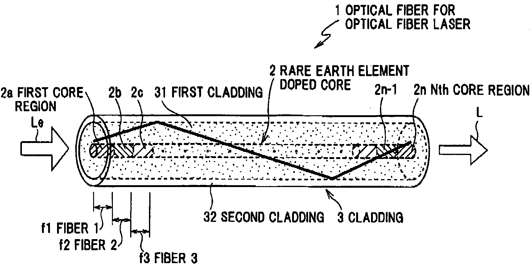
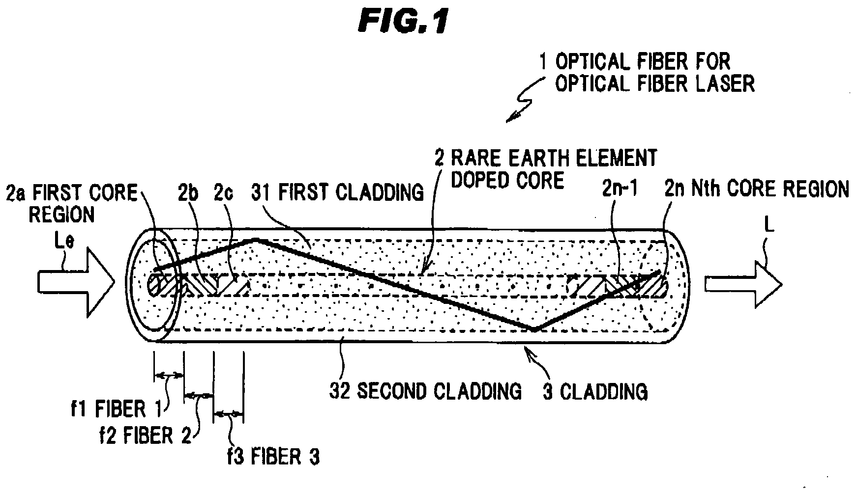
[0055]FIG. 7 is a schematic diagram of the optical fiber laser using the optical fiber for an optical fiber laser as shown in FIG. 1.

[0056]As shown in FIG. 7, an optical fiber laser 71 in a preferred embodiment according to the invention comprises an optical part 72 having a light source for outputting a laser exciting light L, and driving unit such as a laser diode (LD) driver (not shown) that is connected to the optical part 72 for driving the light source.

[0057]The optical part 72 comprises an optical fiber 1 for an optical fiber laser in the preferred embodiment, and first and second light sou...


PUM

PropertyMeasurementUnit
Temperatureaaaaaaaaaa
Fractionaaaaaaaaaa
Fractionaaaaaaaaaa

Abstract

The optical fiber 1 for an optical fiber laser is provided with a rare earth element doped core 2 doped with a rare earth element, and a cladding 3 formed at an outer periphery of the rare earth element doped core 2. In the optical fiber 1 for an optical fiber laser, the rare earth element doped core 2 is divided into a plurality of core regions 2a, 2b, . . . , 2n−1, 2n along a longitudinal direction of the optical fiber 1 and dopant concentrations of the rare earth element in respective core regions 2a, 2b, . . . , 2n−1, 2n are different from each other, in order to flatten a temperature distribution of the optical fiber 1 along the longitudinal direction.

Description

[0001]The present application is based on Japanese Patent Application Nos. 2007-195573 filed on Jul. 27, 2007, the entire contents of which are incorporated herein by reference.BACKGROUND OF THE INVENTION[0002]1. Field of the Invention[0003]The present invention relates to an optical fiber for an optical fiber laser, a method for fabricating the same, and an optical fiber laser, in more particular, to an optical fiber for a high output power optical fiber laser having a rare earth element doped core and a cladding, a method for fabricating the same, and an optical fiber laser.[0004]Development of a less expensive light source with a higher output power has been required for laser processing, medical application, and the like. For these requirements, an optical fiber laser has been noted since it is possible to easily extract a laser light with high efficiency and high quality.[0005]FIG. 9 shows an optical fiber 91 to be used for a high output power optical fiber laser. This optical ...

Claims


Application Information

Patent Timeline
IPC IPC(8): H01S3/02G02B6/02B29C65/00
CPCH01S3/0672H01S3/06716
Inventor YAO, BINGKOJIMA, SEIJIOHSONO, KAZUMASAHONGO, AKIHITO
Owner HITACHI CABLE
Why Eureka
Try Eureka