
Relief printing plate and printed matter

Inactive Publication Date: 2009-04-02
TOPPAN PRINTING CO LTD
View PDF15 Cites 0 Cited by
  • Summary
  • Abstract
  • Description
  • Claims
  • Application Information

AI Technical Summary

Benefits of technology

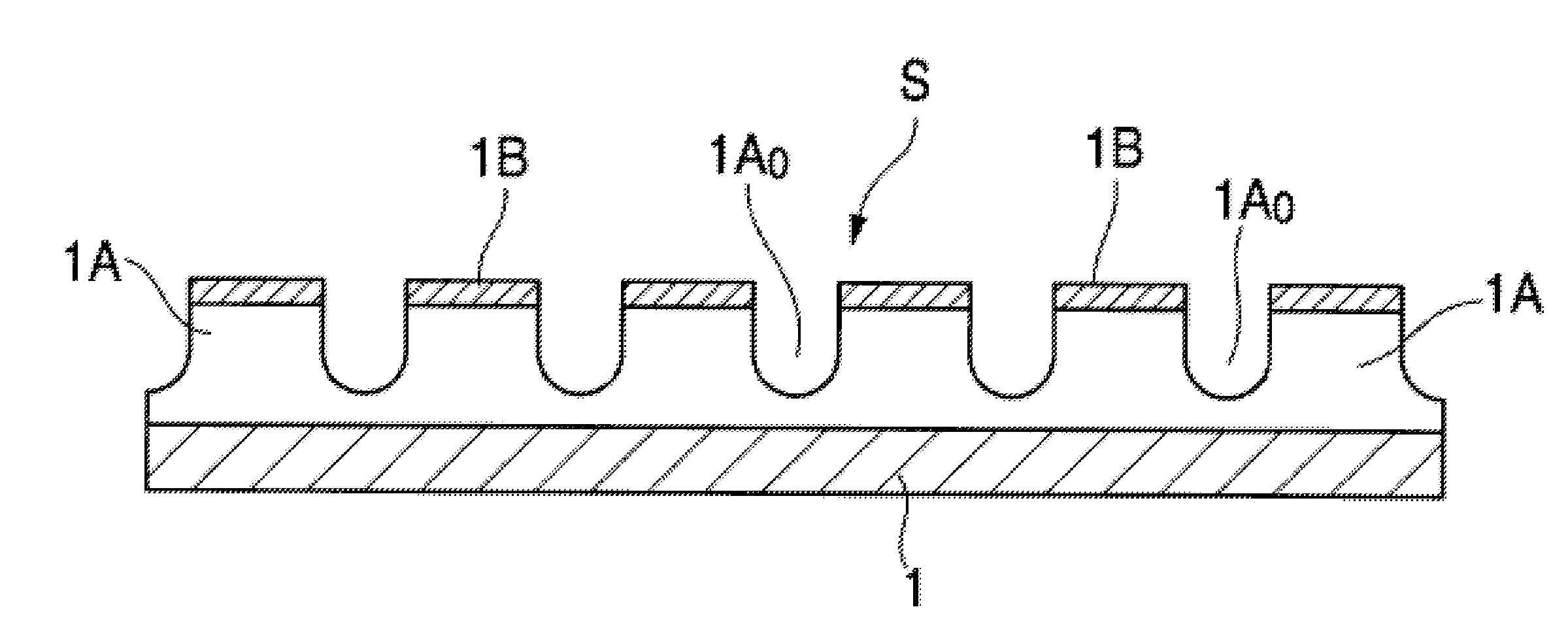
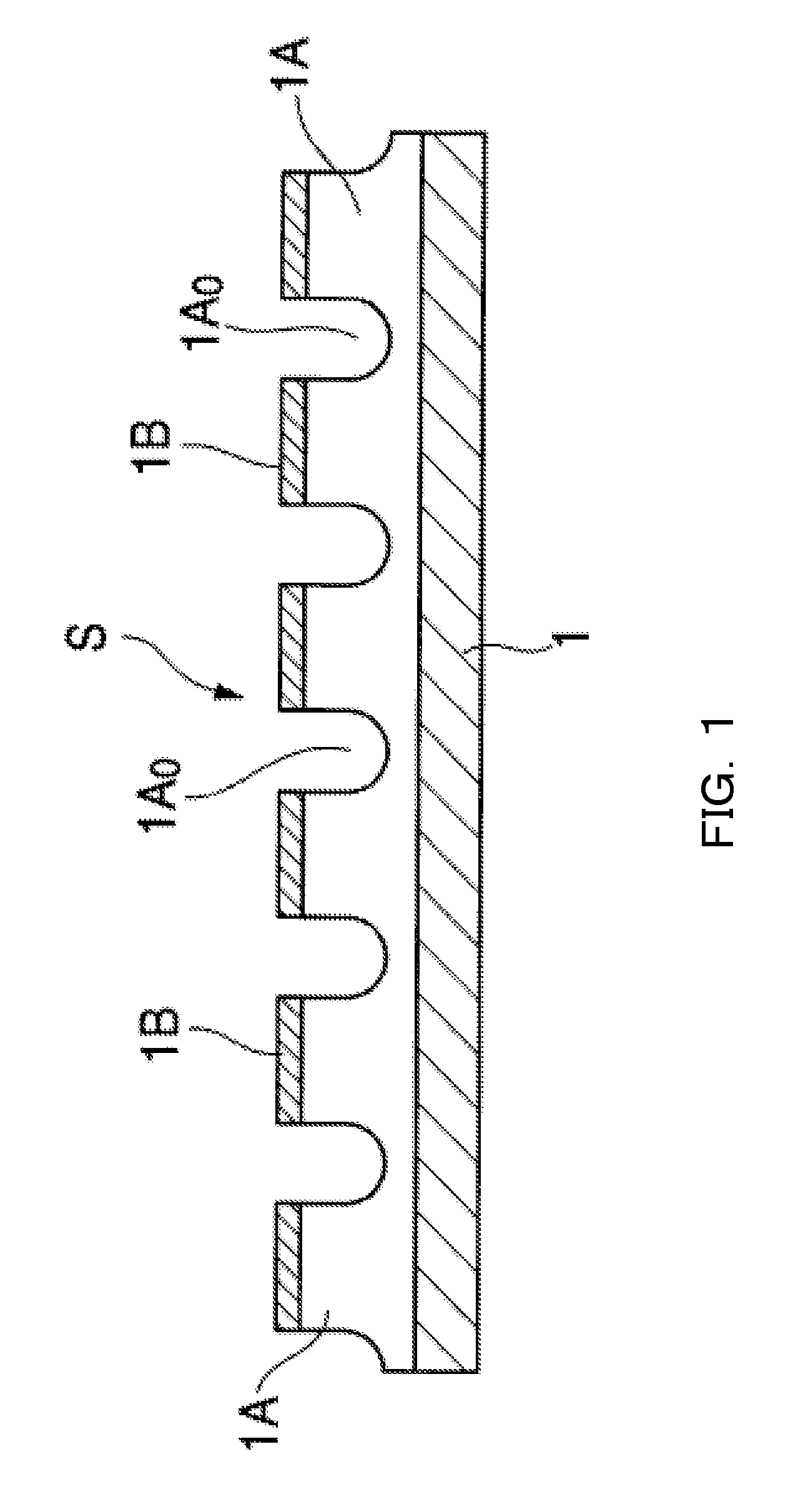
[0017]An object of the present invention is to solve a problem of low repeatability in printing when an ink having low viscosity is printed using a relief printing plate. One embodiment of the present invention is a relief printing plate having a convex part, wherein a top surface of the convex part, which touches

Problems solved by technology

However, this method has a problem that patterning accuracy is reduced with an increase in the size of a substrate.
However, the wet coating methods have difficulty in realizing high definition patterning and color coding with R, G, and B, and it is considered that the thin film is most effectively formed by a printing process that is capable of achieving excellent color coding and patterning.
Thus, a method that uses a metal hard printing plate such as a gravure printing method is unsuitable.
If a content of solid is beyond the max content, an organic light emitting materi

Method used


Image

  • Relief printing plate and printed matter
  • Relief printing plate and printed matter
  • Relief printing plate and printed matter

Examples


reference example 1

A Case where a Water Solubility Polymer was not used for Top Surface 1B

[0072]By the almost same method as example 1, laminate material S0 was formed to manufacture a relief printing plate. An ink liquid for forming a light emitting layer was printed using the relief printing plate, thereby an organic light emitting element which was a light emitting layer substrate for a cathode was manufactured. However, a water solubility polymer was not used for top surface 1B.

reference example 2

A Case where Fluorine was not used for Convex Part 1A

[0073]By the almost same method as example 1, laminate material S0 was formed to manufacture a relief printing plate. An ink liquid for forming a light emitting layer was printed using the relief printing plate, thereby an organic light emitting element which was a light emitting layer substrate for a cathode was manufactured. However, fluorine was not used for convex part 1A.

[0074]When an electric voltage was, through an ITO film, applied to an organic light emitting element manufactured in Example 1 to observe a light emitting state, the film thickness of a light emitting layer was even and unevenness in emitting light was not observed. When an electric voltage was, through ITO film, applied to organic light emitting elements manufactured in Reference Examples 1, 2 to observe a light emitting state, unevenness in light emitting due to unevenness of film thickness was observed.


PUM


Abstract

A relief printing plate has a convex part, wherein a top surface of the convex part, which touches a substrate, comprises a resin layer having an affinity for an ink liquid including an organic light emitting material and the convex part or a convex part forming layer including the convex part, which supports the resin layer, comprises an ink repellent layer which has non-affinity for the ink.

Description

BACKGROUND OF THE INVENTION[0001]1. Field of the Invention[0002]The present invention relates to a relief printing plate used for printing that uses an ink material to form a pattern on a substrate for precision components such as an organic electroluminescence (EL) element and relates to a printed matter formed by using the relief printing plate.[0003]2. Description of the Related Art[0004]An organic EL element emits light when a current is supplied to a light emitting layer which is formed from an organic light emitting material and between two opposed electrodes. In order to achieve efficient light emission, it is important to keep a film thickness of the light emitting layer to about 100 nm. Further, in the case of forming a display from the organic EL element, it is necessary to perform patterning on the organic EL element with high definition.[0005]As the organic light emitting material for the light emitting layer formed on a substrate or the like, a low molecular material an...

Claims


Application Information

Patent Timeline
IPC IPC(8): B41N1/12
CPCB41N1/12B41N1/003
Inventor KAWAKAMI, HIRONORITAKESHITA, KOJISHIMIZU, TAKAHISAINOKUCHI, NAHOKO
Owner TOPPAN PRINTING CO LTD
Learn More