Cylinder head

a cylinder head and cylinder head technology, applied in valve drives, machines/engines, mechanical equipment, etc., can solve the problems of increasing production costs, increasing the number of parts involved, and difficulty in reducing the size of engines to a sufficiently small level, so as to achieve compactness and increase rigidity

Active Publication Date: 2009-04-02
MITSUBISHI MOTORS CORP
View PDF4 Cites 50 Cited by
  • Summary
  • Abstract
  • Description
  • Claims
  • Application Information

AI Technical Summary

Benefits of technology

[0013]It is therefore an object of the invention to provide a cylinder head which can be made compact while increasing its rigidity.

Problems solved by technology

It is considered that the disposition of such ribs in the cylinder head makes it difficult to reduce the size of the engine to a sufficiently small level.
Furthermore, in the event that the support wall and the lower bearing member are made up of the separate parts as with the construction disclosed in Japanese Patent No. 3263118, an increase in production costs is called for due to an increase in the number of parts involved.

Method used


Image

  • Cylinder head
  • Cylinder head
  • Cylinder head

Examples


Embodiment Construction

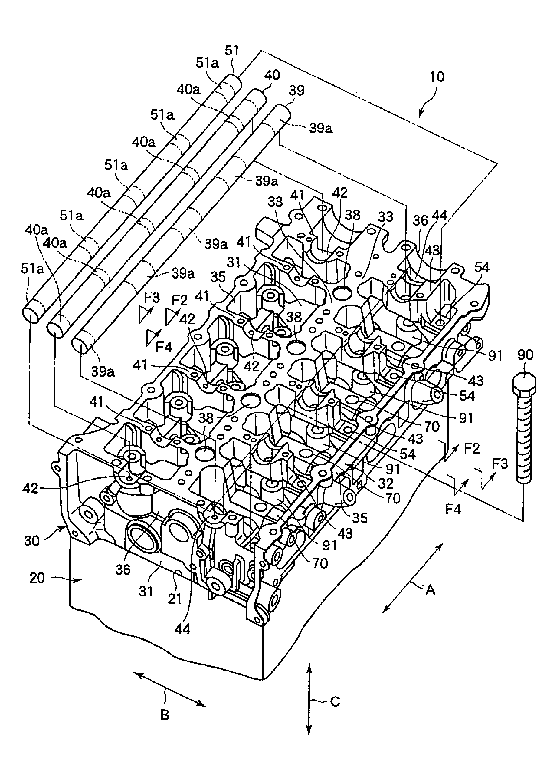
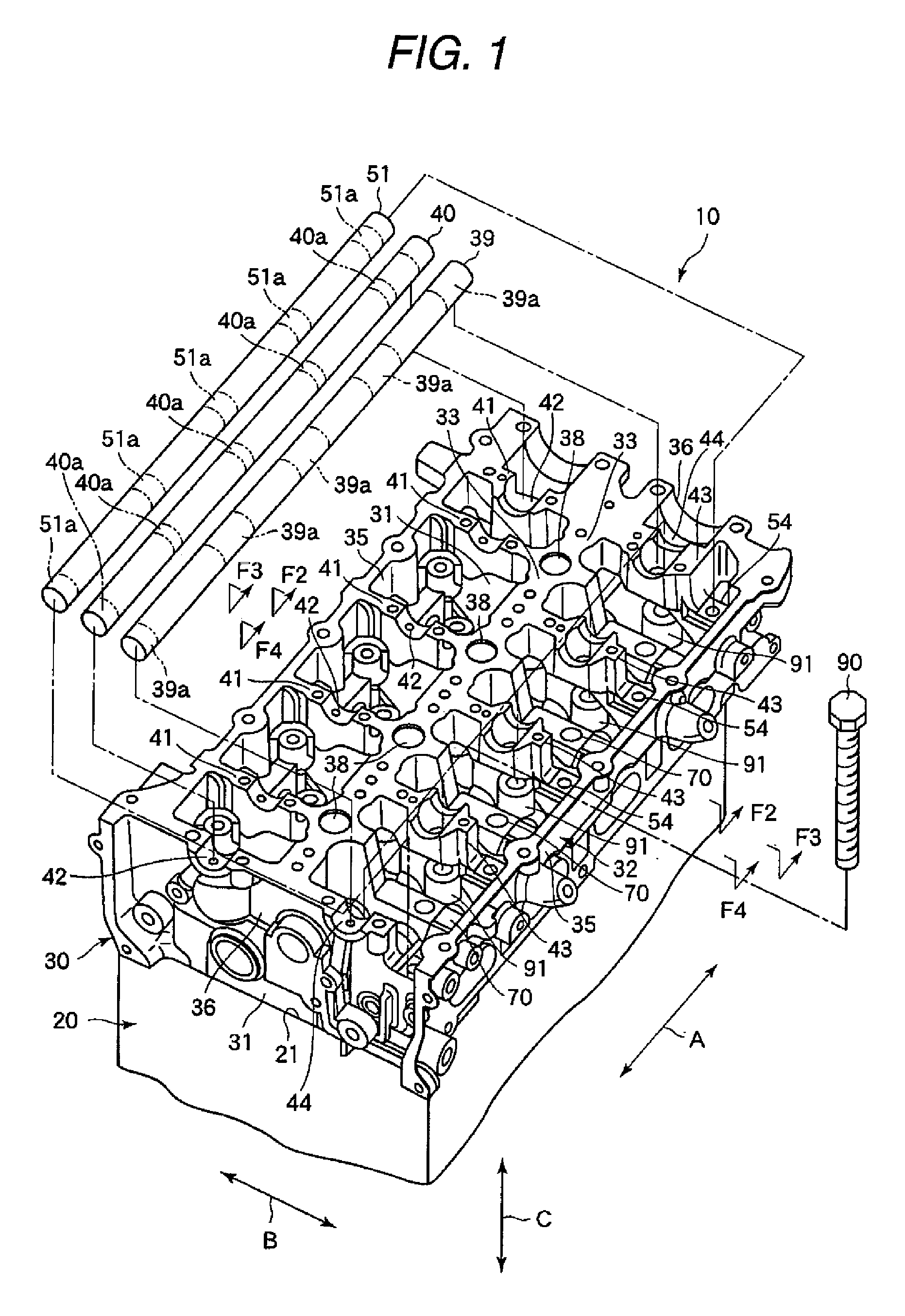
[0038]A cylinder head according to an embodiment of the invention will be described using FIGS. 1 to 6. FIG. 1 is a perspective view showing schematically an engine 10 which includes a cylinder head 30 of the embodiment.

[0039]As is shown in FIG. 1, the engine is, for example, an in-line four-cylinder diesel engine. The engine 10 includes a cylinder block 20 and a cylinder head 30. FIG. 5 is a sectional view showing schematically an interior of the cylinder block 20. As is shown in FIG. 5, cylinders 22 are formed within the cylinder block 20. Pistons 23 are accommodated in the cylinders 22. Connecting rods, not shown, are connected to the pistons 23, respectively, and these connecting rods are connected to a crankshaft, not shown.

[0040]Combustion chambers 24 are formed between the respective pistons 23 and the cylinder head 30, which will be described later. The pistons 23 are put in motion by energy produced within the combustion chambers 24 in the power stroke, and such motions of ...


PUM


Abstract

A cylinder head includes: a bottom wall portion; an outer circumferential wall portion defining inside thereof a disposition space where valves which open and close combustion chambers, rocker arms, a camshaft which actuates the rocker arms, and a rocker arm shaft which supports the rocker arms are disposed; a longitudinal wall portion; a lateral wall portion, integrally formed with the longitudinal wall portion and the outer circumferential wall portion; a camshaft support portion, formed on the lateral wall portion; a rocker arm shaft support portion, formed on the lateral wall portion in such a manner that a height position of the rocker arm shaft is shifted from a height position of the camshaft; and a head bolt boss portion, formed on the bottom wall portion in such a manner as to overlap the lateral wall portion in a height direction. The lateral wall portion includes a passage portion through which a head bolt is passed into the head bolt boss portion and which overlaps the head bolt boss portion in the height direction.

Description

BACKGROUND OF THE INVENTION[0001]The present invention relates to a cylinder head of an engine.[0002]In general, a cylinder head of an engine is built on an upper side of a cylinder block with head bolts, and intake valves for opening and closing intake ports of combustion chambers, exhaust valves for opening and closing exhaust ports of the combustion chambers, a camshaft and rocker arms which actuate the intake and exhaust valves to open and close the intake and exhaust ports, a rocker arm shaft which supports the rocker arms and the like are provided on the cylinder head. The rotation of a crankshaft is transmitted to the camshaft via timing gears or a timing belt.[0003]Pluralities of camshaft support portions for supporting the camshaft rotatably and rocker arm shaft support portions for supporting the rocker arm shaft rotatably are provided on the cylinder head. Specifically, these camshaft support portions and rocker arm support portions are each formed into a concave shape (a...

Claims


Application Information

Patent Timeline
Patent Type & Authority Applications(United States)
IPC IPC(8): F02F1/00
CPCF02F2007/0063F02F1/24F01L1/04F02F1/00
Inventor KOMURA, KEISUKEOKA, TOSHIHIKOMORISHIMA, KENICHITAKAYASU, NORIO
Owner MITSUBISHI MOTORS CORP
Why Eureka
Try Eureka