Diaphragm Based Spontaneous Inflation Inhibitor in a Pump for an Inflatable Prosthesis

a technology of spontaneous inflation and diaphragm, which is applied in the direction of mechanical equipment, water supply installation, transportation and packaging, etc., can solve the problems of increasing the fluid pressure which is transferred to the inflatable cylinder, and the pressure generated by compressing the pump bulb will far exceed the level of overpressure, so as to achieve less pressure, increase the surface area, and increase the effect of surface area

Inactive Publication Date: 2009-04-02
BOSTON SCI SCIMED INC
View PDF100 Cites 9 Cited by
  • Summary
  • Abstract
  • Description
  • Claims
  • Application Information

AI Technical Summary

Benefits of technology

[0017]The present invention includes a penile pump having a dual poppet arrangement wherein the poppets act as check valves or flow valves. Each poppet is spring-biased against a valve seat, and under normal circumstances, only allows positive fluid flow when a pump bulb is operated, thus causing an increase in fluid pressure which is transferred to the inflatable cylinders. To prevent spontaneous inflation when an overpressurization occurs in the reservoir, the same reservoir pressure is utilized to seal the fluid output against itself or to seal one or both of the poppets against the valve seat. Thus, the fluid is prevented from reaching the cylinders and creating a spontaneous inflation. When the movement or activity generating the overpressure in the reservoir is released, the system should return to equilibrium. Even if overpressurization of the reservoir is occurring, the pressure generated by compressing the pump bulb will far exceed the level of overpressure. Thus, the poppets will open in the normal way, allowing fluid to flow to the cylinders. The use of the overpressure in the reservoir itself to prevent fluid flow to the cylinders can occur in a variety of formats.
[0018]In still another embodiment, the reservoir poppet is actually coupled to an outer wall defining a portion of the fluid input. When an overpressurization in the reservoir occurs, this outer wall is forced to expand which simultaneously causes the reservoir poppet to be pulled firmly against the valve seat. This effectively prevents fluid flow from reaching the cylinders and causing a spontaneous inflation.
[0019]In yet another embodiment of the present invention, the valve seat is provided with a flexible valve which cooperates with the first poppet to prevent spontaneous inflation which could be caused by excessive pressure in the reservoir. Specifically, pressure in the reservoir and associated valve input is presented to the flexible valve and thus causing the valve to be further forced against the poppet, thus sealing off the input. When inflation is desired however, the negative pressure pulling the first poppet away from the valve seat will allow the desired fluid flow.

Problems solved by technology

Each poppet is spring-biased against a valve seat, and under normal circumstances, only allows positive fluid flow when a pump bulb is operated, thus causing an increase in fluid pressure which is transferred to the inflatable cylinders.
Even if overpressurization of the reservoir is occurring, the pressure generated by compressing the pump bulb will far exceed the level of overpressure.

Method used


Image

  • Diaphragm Based Spontaneous Inflation Inhibitor in a Pump for an Inflatable Prosthesis
  • Diaphragm Based Spontaneous Inflation Inhibitor in a Pump for an Inflatable Prosthesis
  • Diaphragm Based Spontaneous Inflation Inhibitor in a Pump for an Inflatable Prosthesis

Examples


first embodiment

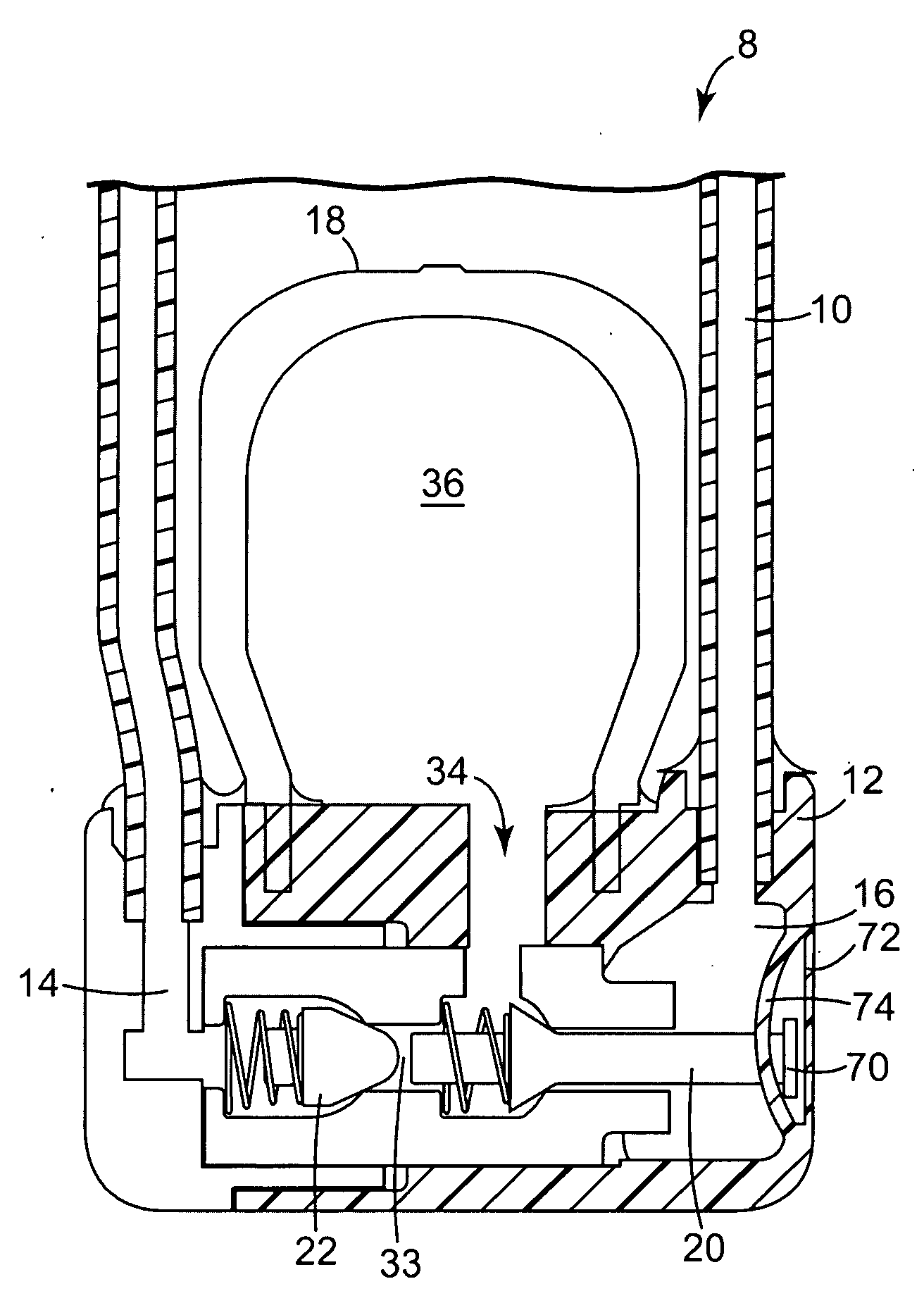
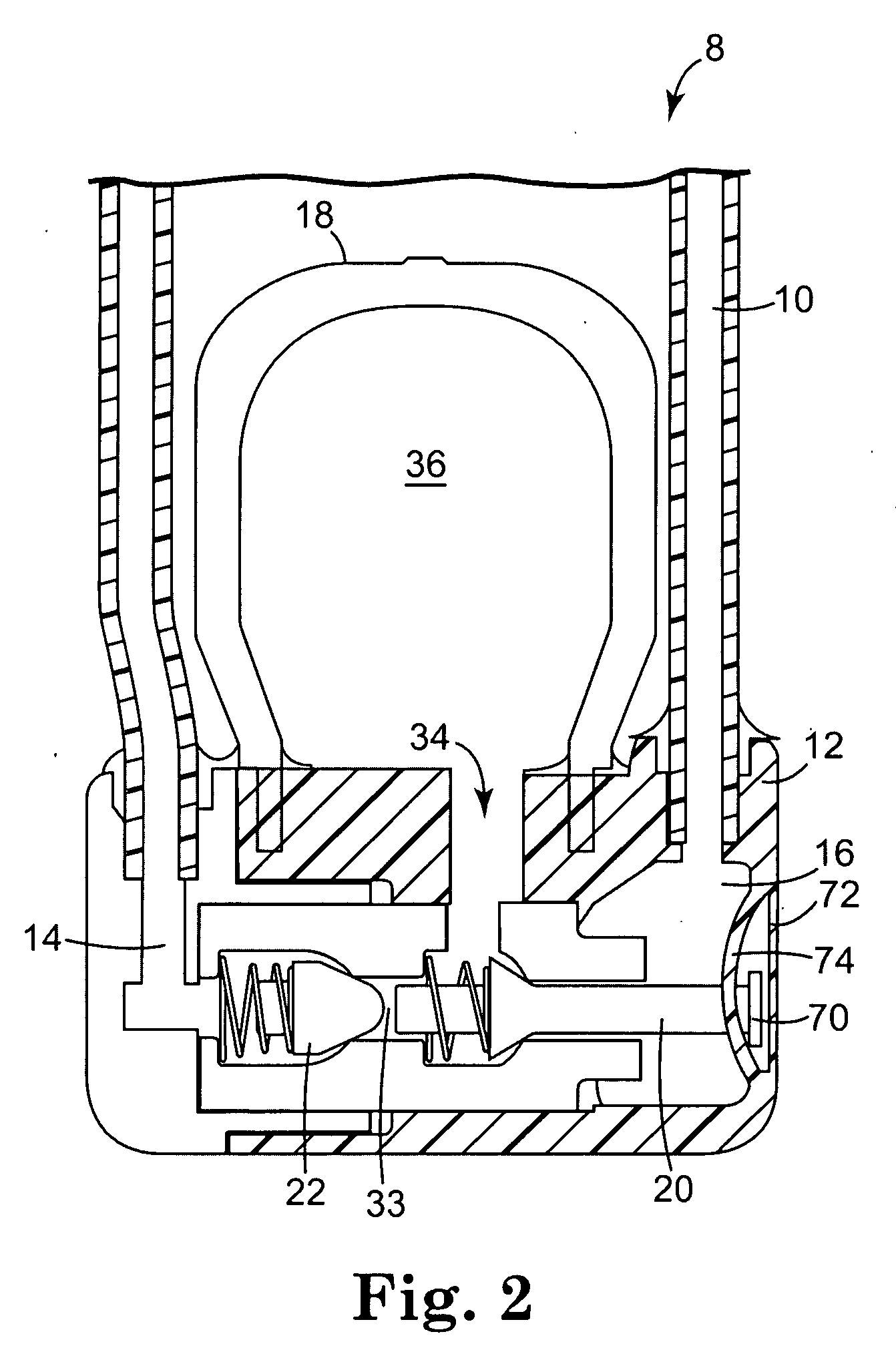
[0081]Referring to FIG. 2, the present invention is illustrated. A fluid input 10 couples a reservoir to reservoir chamber 16. Reservoir poppet 20 has been modified to include a T-shaped tip 70. Tip 70 is secured to an outer reservoir chamber wall 72. Tip 70 is secured to the outer reservoir chamber wall by one or more connecting bands 74. Sufficient freedom of movement for reservoir poppet 20 is provided so that during normal operation reservoir poppet 20 can be dislodged from its abutment with reservoir poppet valve seat 24.

[0082]During an overpressure situation, the reservoir is compressed, pressurizing the fluid and directing it through fluid input 10 and into reservoir chamber 16. Outer reservoir chamber wall 72 has been made sufficiently flexible so that when this occurs, reservoir chamber 16 is caused to expand due to the increased pressure generated. As outer reservoir chamber wall 72 expands, connecting bands 74 coupled with tip 70 pull reservoir poppet 20 tightly against r...

second embodiment

[0084]Referring to FIG. 4, the present invention is illustrated. FIG. 4 illustrates the portion of housing 12 containing reservoir poppet 20 and cylinder poppet 22. Reservoir poppet 20 is an elongated member that terminates in a nose 82. A tapered reservoir passageway 84 is provided through a sidewall 80 located adjacent to fluid input 10. Located at the junction of the sidewall 80 and reservoir passageway 84 is a flap 78 that is able to flex, with respect to sidewall 80. Flap 78 is simply the terminus of sidewall 80 at the passageway 84, and will optimally be offset by some angle from the remainder of the sidewall 80.

[0085]As illustrated in FIG. 4, reservoir poppet 20 is in a sealed position. That is, fluid is not able to pass from fluid input 10 through tapered passageway 84 and beyond, because reservoir poppet 20 is sealed against sidewall 80 at reservoir poppet valve seat 24 and is held in place by spring 28. In addition, nose 82 of reservoir poppet 20 contacts flap 78, providin...

third embodiment

[0088]Referring to FIG. 5, a third embodiment is illustrated. Reservoir poppet 20 is an elongated member that extends from common passageway 33, through poppet passageway 92 and into fluid input 10. As with many of the above embodiments, in one position the reservoir poppet 20 abuts reservoir poppet valve seat 24. Similarly, reservoir poppet 20 is only expected to be removed from valve seat 24 during a re-expansion of a compressed pump bulb 18. To prevent the removal of the reservoir poppet from valve seat 24 during an overpressure situation, relief area 90 has been formed within the housing 12. Formation of relief area 90 creates a flexible valve 88. Flexible valve 88 forms a part of the reservoir poppet valve seat 24, and appears as shown in FIG. 5, under normal circumstances.

[0089]FIG. 6 illustrates an overpressure situation where the pressure of the fluid in fluid input 10 and poppet passageway 92 is relatively high. Rather than forcing reservoir poppet 20 from valve seat 24, th...


PUM


Abstract

A method of preventing inadvertent inflation of an implantable prosthetic includes biasing a valve assembly such that an outlet is substantially closed and using inadvertent pressure increases from the inlet to supplement the biasing of the valve assembly. It may further include the step of preventing fluid flow through the outlet by selectively varying fluid pressure within a bypass passageway having a first end which is in fluid communication with an inlet and a second end which is in fluid communication with a chamber. And, may also additionally include the step of displacing a flexible abutting wall disposed between the chamber and the valve assembly so that the abutting wall is caused to contact the valve assembly and urge the valve assembly into a closed position when the fluid pressure within the chamber exceeds a predetermined amount.

Description

REFERENCE TO RELATED APPLICATIONS[0001]The present application is a divisional patent application of U.S. Ser. No. 10 / 821,232, filed Apr. 8, 2004, now U.S. Pat. No. 7,438,682, which is a divisional patent application of U.S. Ser. No. 10 / 010,498, filed Dec. 3, 2001, now U.S. Pat. No. 6,730,017, which claims priority to U.S. Prov. Ser. No. 60 / 295,326, filed Jun. 1, 2001 and is also a continuation-in-part patent application of U.S. Ser. No. 09 / 749,292, filed Dec. 27, 2000, now abandoned. Each of the identified patent applications and patents are hereby incorporated by reference.BACKGROUND[0002]This invention generally relates to a pump and valve assembly for inflating a prosthesis. More particularly, the invention relates to pressure based mechanisms that inhibit spontaneous inflation of the prosthesis, including stiffening and support mechanisms that also improve the function of the valve.[0003]One common treatment for male erectile dysfunction is the implantation of a penile prosthes...

Claims


Application Information

Patent Timeline
Patent Type & Authority Applications(United States)
IPC IPC(8): A61B17/00A61F2/26
CPCA61F2/26Y10T137/0379
Inventor HENKEL, GREGORY J.WALDACK, LARRY E.KUYAVA, CHARLES C.MORNINGSTAR, RANDY L.ALMLI, JOHN G.
Owner BOSTON SCI SCIMED INC
Why Eureka
Try Eureka