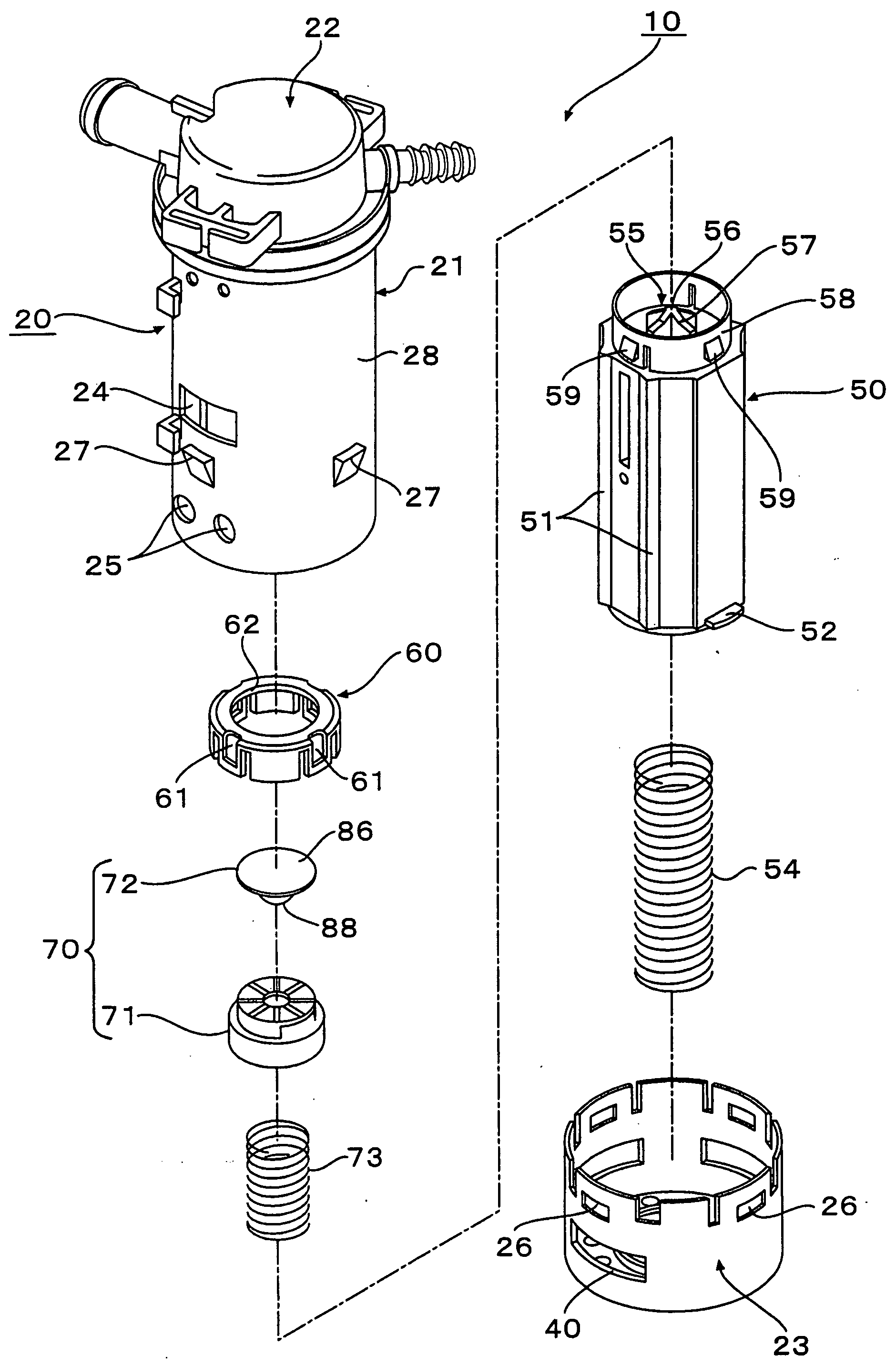
Float valve device

a technology of float valve and float body, which is applied in the direction of valve operating means/releasing devices, liquid fuel feeders, machines/engines, etc., can solve the problems of increasing the space required for disposing of the valve member, increasing the risk of cracking and the like, and enhancing the sealing surface of the movable valve and the receiving portion. , to achieve the effect of enhancing the effect of preventing the breakage of the movable portion and the flexibility of the sealing surfa

Active Publication Date: 2009-04-02
PIOLAX CO LTD
View PDF13 Cites 14 Cited by
  • Summary
  • Abstract
  • Description
  • Claims
  • Application Information

AI Technical Summary

Benefits of technology

[0019]According to the fifth aspect, the cavity is provided in the rib that couples the plate portion on which the receiving portion is formed and the upper plate portion that constitutes the sealing surface to each other, whereby the flexibility between the sealing surface of the movable valve and the receiving portion is far more enhanced, and the impact force when the protruding portion of the float collides with the receiving portion is relieved more effectively, thus making it possible to enhance the effect of preventing the breakage of the movable portion.
[0020]According to the present invention, when the float rises and the protruding portion of the float abuts on the receiving portion of the movable valve, the periphery of the top portion of the protruding portion abuts on the inner circumference periphery of the center hole of the receiving portion. Accordingly, the impact force when the protruding portion collides with the receiving portion is dispersed to the periphery of the center hole, and is avoided from being concentrated on one spot of the receiving portion. Further, the flexibility is imparted to the receiving portion by the center hole. Therefore, even in the case where strong impact force caused by falling and the like acts on, for example, at the time of conveying components, the breakage such as the crack can be prevented from occurring in the movable valve.

Problems solved by technology

Hei 07-279789, it has been found out that, when the float rises and abuts on the valve seat through an intermediation of the valve member, the top portion of the float strongly abuts on the valve member, causing a risk that a crack and the like may occur in the valve member.
It has been found out that, in particular, in the case where this component (float valve device) is dropped while being handled at the time of being conveyed, the top portion of the float collides with the valve member, and makes a strong impact thereon, and accordingly, the above-mentioned risk of the crack is increased.
However, a space for disposing the valve member thus increased in size becomes necessary, and there has been a problem that the float valve device is increased in size.

Method used


Image

  • Float valve device
  • Float valve device
  • Float valve device

Examples


examples

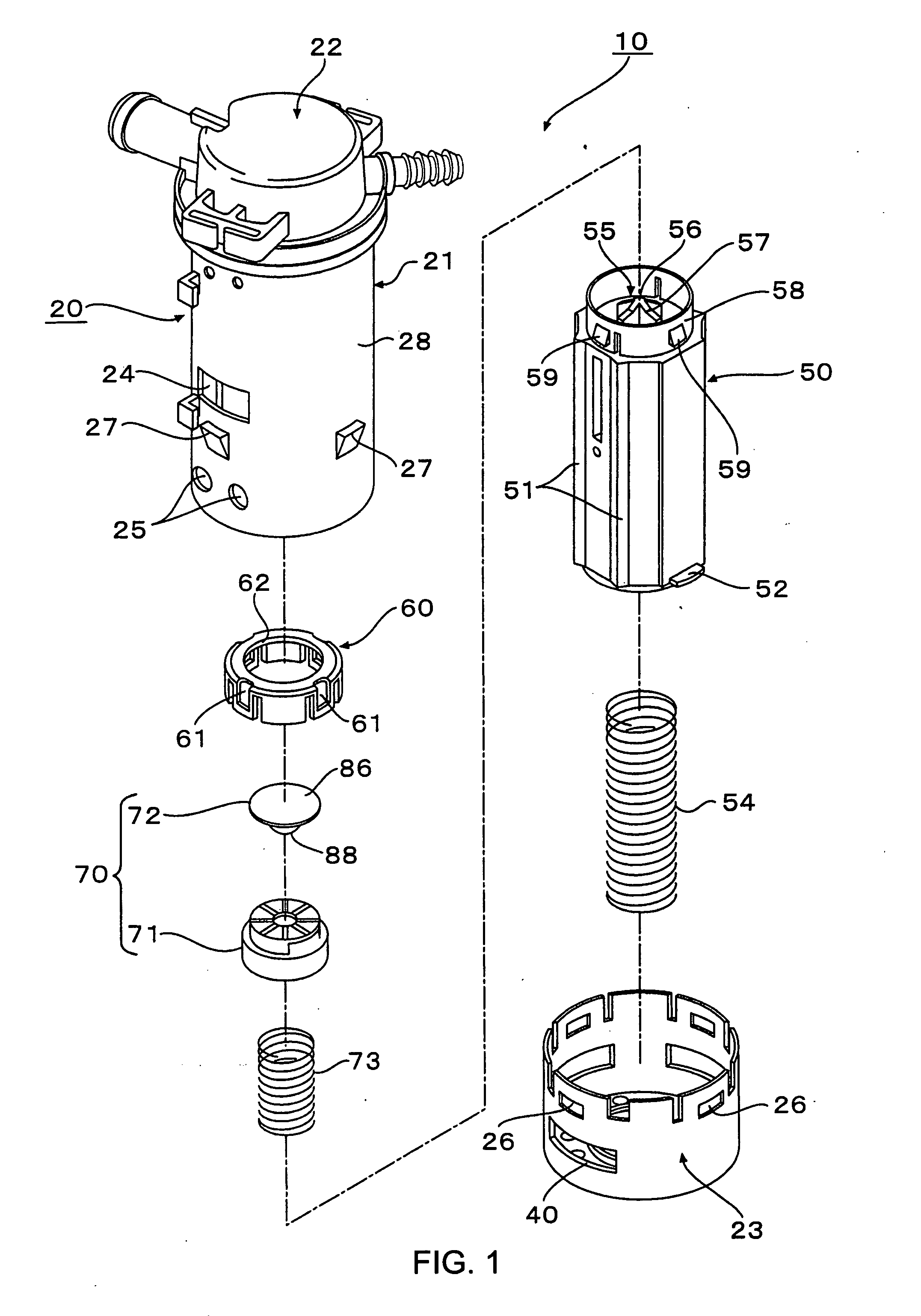
[0060]With regard to the float valve device illustrated in FIG. 1 to FIG. 8C, experimentally made were: ones (Example 1) in each of which the inner diameter of the center hole 83 of the receiving portion 81 of the movable valve 70 was set at 3 mm; and ones (Example 2) in each of which the inner diameter of the center hole 83 was set at 3 mm in the same way, and the center hole 83 was made as the through hole as illustrated in FIG. 6D.

[0061]Note that glass fiber reinforced aromatic Nylon (glass fiber content: 30%) was used as a material of the housing20, the float 50, and the movable valve 70. Further, with regard to a size of the float 50, an outer diameter thereof was set at 29 mm, a length thereof was set at 75 mm, a weight thereof was set at 45 g. A thickness of the annular protruding portion 82 of the receiving portion 81 of the movable valve 70 was set at 2.1 mm, and a thickness of the outer circumference of the center hole 83 was set at 0.8 mm.

[0062]Meanwhile, ones (Comparativ...


PUM


Abstract

Provided is a float valve device that closes an opening portion by pushing a movable valve by means of a protruding portion formed on an upper portion of a float, in which a problem of a crack and the like of the movable valve can be solved without thickening the movable valve or increasing the movable valve in size. A space in a housing is defined into a lower space and an upper space through an intermediation of a partition wall, and an opening portion is provided in the partition wall. A float is housed in the lower space of the housing so as to be vertically slidable, and to an upper portion of the float, a movable valve is mounted so as to be movable relatively to the float in a vertical direction and a lateral direction. A protruding portion is provided on the upper portion of the float, and a receiving portion on which the protruding portion abuts is provided on a lower surface of the movable valve. A center hole is provided in a center of the receiving portion. When the float comes up, a peripheral portion of a top portion of the protruding portion of the float is adapted to abut on an inner circumference periphery of the center hole.

Description

BACKGROUND OF THE INVENTION[0001]1. Field of the Invention[0002]The present invention relates to a float valve device configured so that a float can come up in a housing when a height of a liquid level of a liquid rises to thereby close an opening portion communicating with an outside when the liquid level reaches a predetermined height. In particular, the present invention relates to one suitable as a float valve device configured so as to dissipate fuel vapor contained in a fuel tank of an automobile to a canister, to prevent fuel from flowing outside of the fuel tank by closing the opening portion when a height of a liquid level of the fuel exceeds a predetermined value, and to regulate the fuel tank from being filled up at the time when the fuel tank is refueled.[0003]2. Description of the Related Art[0004]For example, in a fuel tank of an automobile, there is disposed a float valve device for preventing an inner pressure of the fuel tank from increasing by dissipating fuel vapo...

Claims


Application Information

Patent Timeline
Patent Type & Authority Applications(United States)
IPC IPC(8): F16K31/18
CPCF16K24/044Y10T137/0874Y10T137/3099Y10T137/7358B60K15/01B60K15/077F02M37/00F16K24/00
Inventor MATSUO, SHINICHI
Owner PIOLAX CO LTD
Why Eureka
Try Eureka