Disc brake pad with visual wear indicator

Inactive Publication Date: 2009-04-02
MASTERSON STEVEN J
View PDF12 Cites 17 Cited by
  • Summary
  • Abstract
  • Description
  • Claims
  • Application Information

AI Technical Summary

Benefits of technology

[0015]Yet another object of this invention is to provide a visual indicator of bra

Problems solved by technology

Visual confirmation of automobile brake wear is a problem faced every day by countless drivers.
Currently, automobile mechanics are required to perform a close and time-consuming inspection to ascertain whether brake wear has reached a level warranting replacement of die brake pad.
Thus, the current method of inspecting brake pads for wear is less efficient and more expensive than it otherwise could be if automobile mechanic inspections and parts disassembly were not required.
Thus, when the depth of the grooves becomes very reduced

Method used


Image

  • Disc brake pad with visual wear indicator
  • Disc brake pad with visual wear indicator
  • Disc brake pad with visual wear indicator

Examples


Embodiment Construction

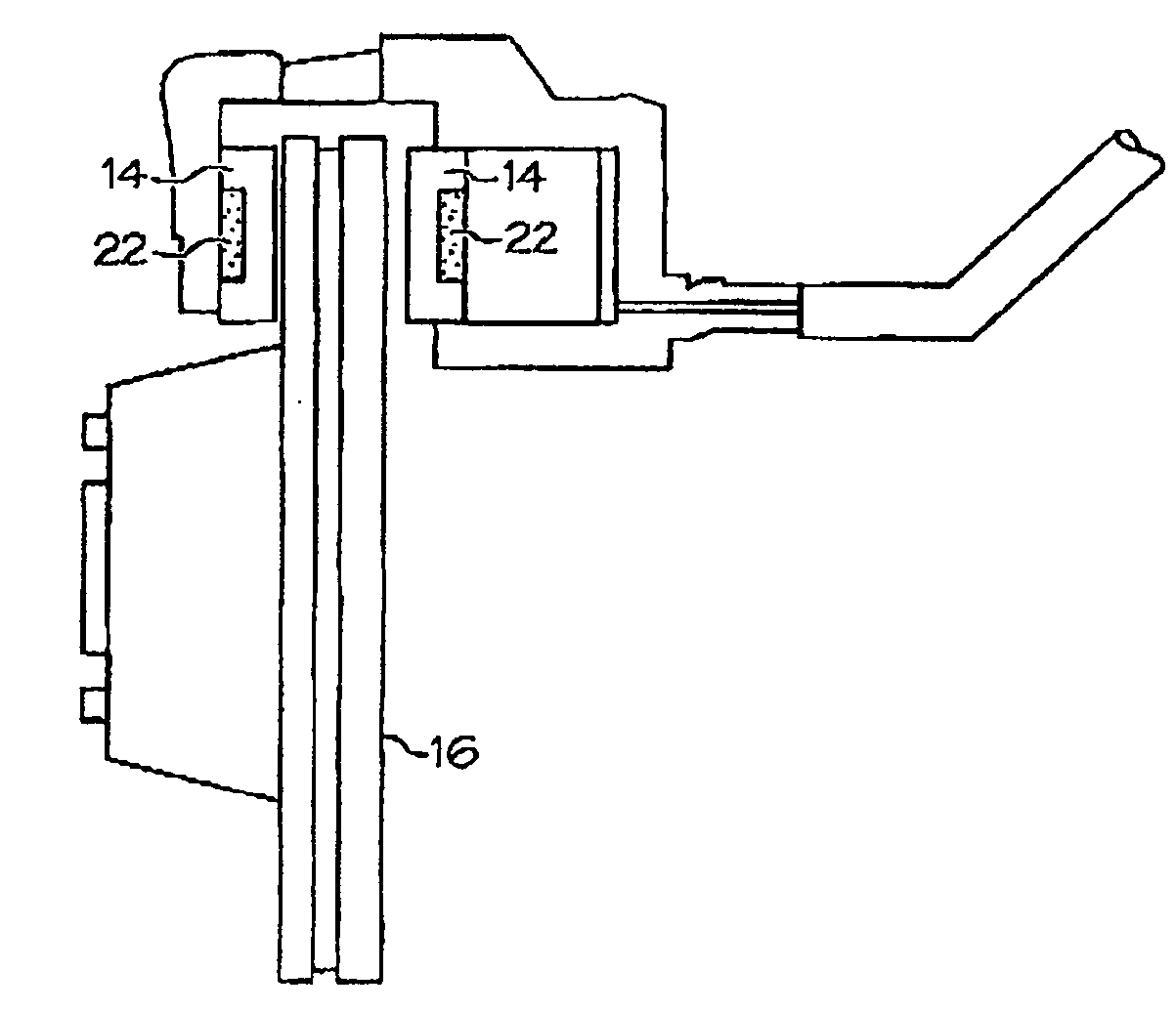
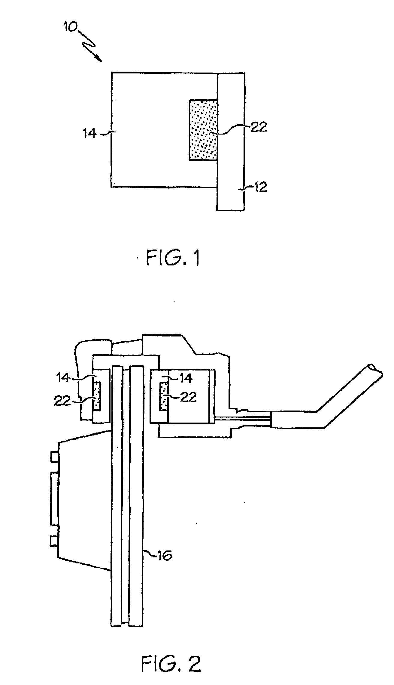
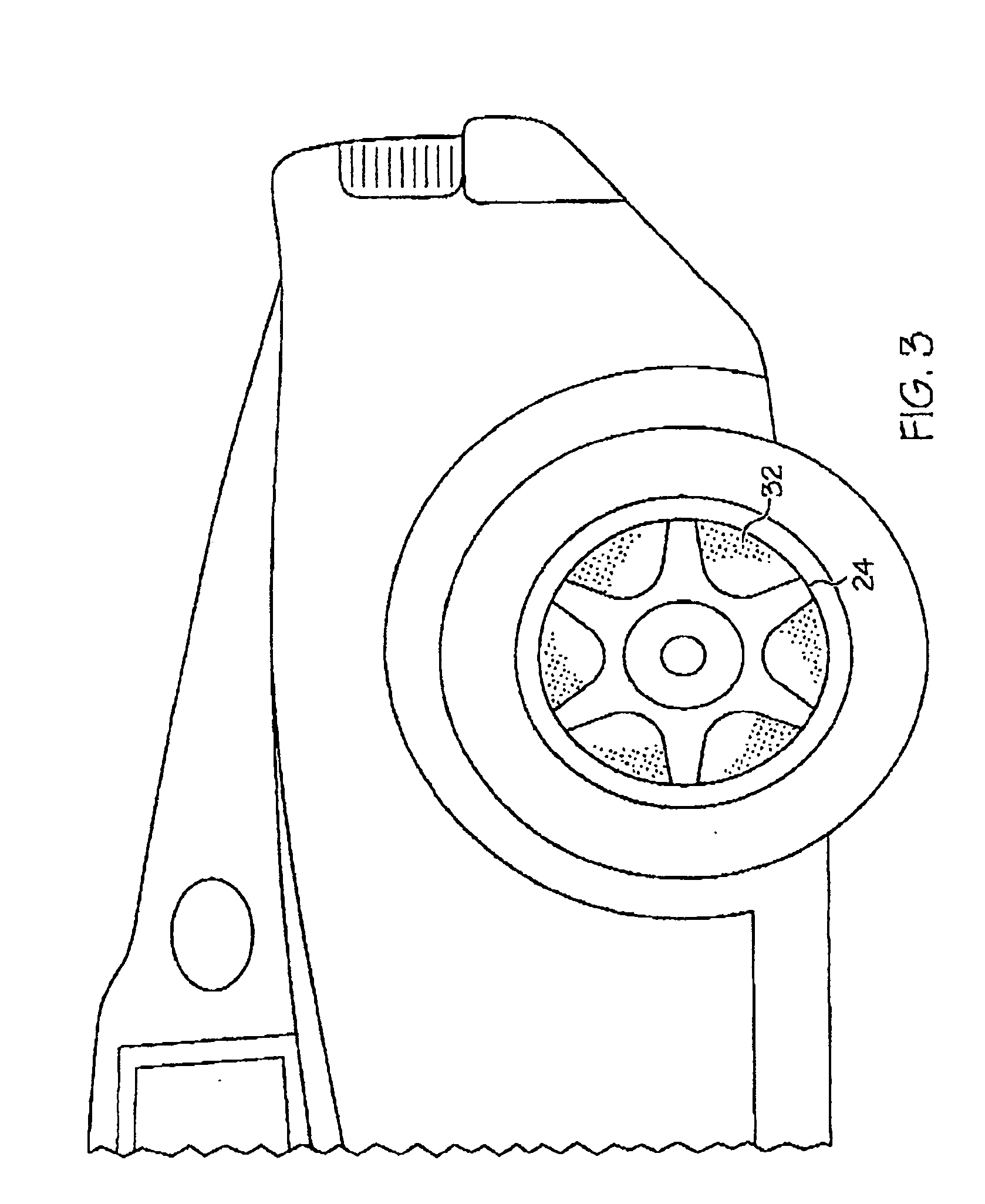
[0024]FIGS. 1 and 2 illustrate an improved disc brake pad 10 comprising a single layer of friction material 14 and a source of visual indicator material 22. The improved disc brake pad 10 provides a visual alert and prompt that the brake pad's friction material 14 has worn away to such an extent that the brake pad will soon become unsafe for driving and possibly prone to brake failure. The source of visual indicator material 22 may include one or more layers of a visual indicator material or materials capable of forming a colored dust 32. In the preferred embodiment of the improved disc brake pad 10, the visual indicator material 22 comprises a thermally-stable, heat-resistant dye, however, other heat-resistant materials capable of forming a colored brake pad dust may also be used. Alternative visual indicator materials may include any suitable thermally-stable, heat-resistant, color-producing, erodable material such as metals, metal alloys, clays, artificial polymers, and heat-resi...


PUM


Abstract

A disc brake pad having a visual indicator of brake wear to eliminate the current necessity of dismantling related parts for brake pad inspection by an automobile mechanic. The improved brake pad uses an existing conventional brake pad friction material having a recess cut into a rear surface of the friction material where the friction material is connected to the brake pad backing. This recess is filled with one or more layers of a brightly-colored visual indicator dye or dyes. As the friction material is worn sway by contact with the brake rotor, the thickness of the friction material is reduced until, eventually, the visual indicator becomes exposed at a predetermined depth. The visual indicator dye is pulverized and discharged onto the exterior surface of the wheel rim as colored brake dust. The presence of the colored brake dust alerts the driver of the need for brake pad replacement.

Description

BACKGROUND OF THE INVENTION[0001]1. Field of the Invention[0002]This invention relates to an article of manufacture comprised of an improved automobile disc brake pad having a visual brake wear indicator that is readily visible.[0003]2. Description of Related Art[0004]Visual confirmation of automobile brake wear is a problem faced every day by countless drivers. Currently, automobile mechanics are required to perform a close and time-consuming inspection to ascertain whether brake wear has reached a level warranting replacement of die brake pad. Oilier related parts of an automobile must be dismantled in order to inspect the brake pads. Due to the numerous factors that can affect the life of a brake pad, most vehicle manufacturers recommend periodic inspections of the brake components. Thus, the current method of inspecting brake pads for wear is less efficient and more expensive than it otherwise could be if automobile mechanic inspections and parts disassembly were not required.[0...

Claims


Application Information

Patent Timeline
IPC IPC(8): F16D66/02
CPCF16D65/092F16D2069/005F16D66/028F16D66/02
Inventor MASTERSON, STEVEN J.
Owner MASTERSON STEVEN J
Why Eureka
Try Eureka