
Lamp

a technology for lamps and light beams, applied in the field of lamps, can solve the problems of low electricity conversion into light, insufficient brightness in locations outside the light beam of lamps, and prior art can't overcome the problem of plurality of shadows

Inactive Publication Date: 2009-04-02
GINGKO LIGHTING
View PDF9 Cites 29 Cited by
  • Summary
  • Abstract
  • Description
  • Claims
  • Application Information

AI Technical Summary

Benefits of technology

[0011]The present invention has advantageous effects as follows. The light-guiding element for light mixing (a.k.a. overlapping of light) is installed between the lampshade and the seat. Thus, the plurality of shadows generated by the LED will be eliminated and the light is brighter and the intensity of light increases. The reflecting layer is disposed between the lampshade and the seat. Thus, the light area will be broadened via the reflecting layer. And then the light is mixed via the light-guiding element. The light generated by the LED will transform from point to plane.
[0012]In order to further understand the characteristics and technical contents of the present invention, a detailed description is made with reference to the accompanying drawings. However, it should be understood that the drawings are illustrative only but not used to limit the present invention thereto.

Problems solved by technology

Traditional Tungsten lamps produces light source that scatters, therefore ensures a certain degree of brightness to the surrounding area, however traditional tungsten lamps has the disadvantage of low electricity conversion into light, thus, there is now a growing trend of replacing the traditional tungsten lamps with light emitting diodes (LEDs).
Thus, the brightness in locations outside of the lamp's light beam may be insufficient.
Although the prior art lamp can increase brightness, but the prior art can t overcome the problem of having a plurality of shadows when using the prior art lamp.

Method used


Image

  • Lamp
  • Lamp
  • Lamp

Examples


Embodiment Construction

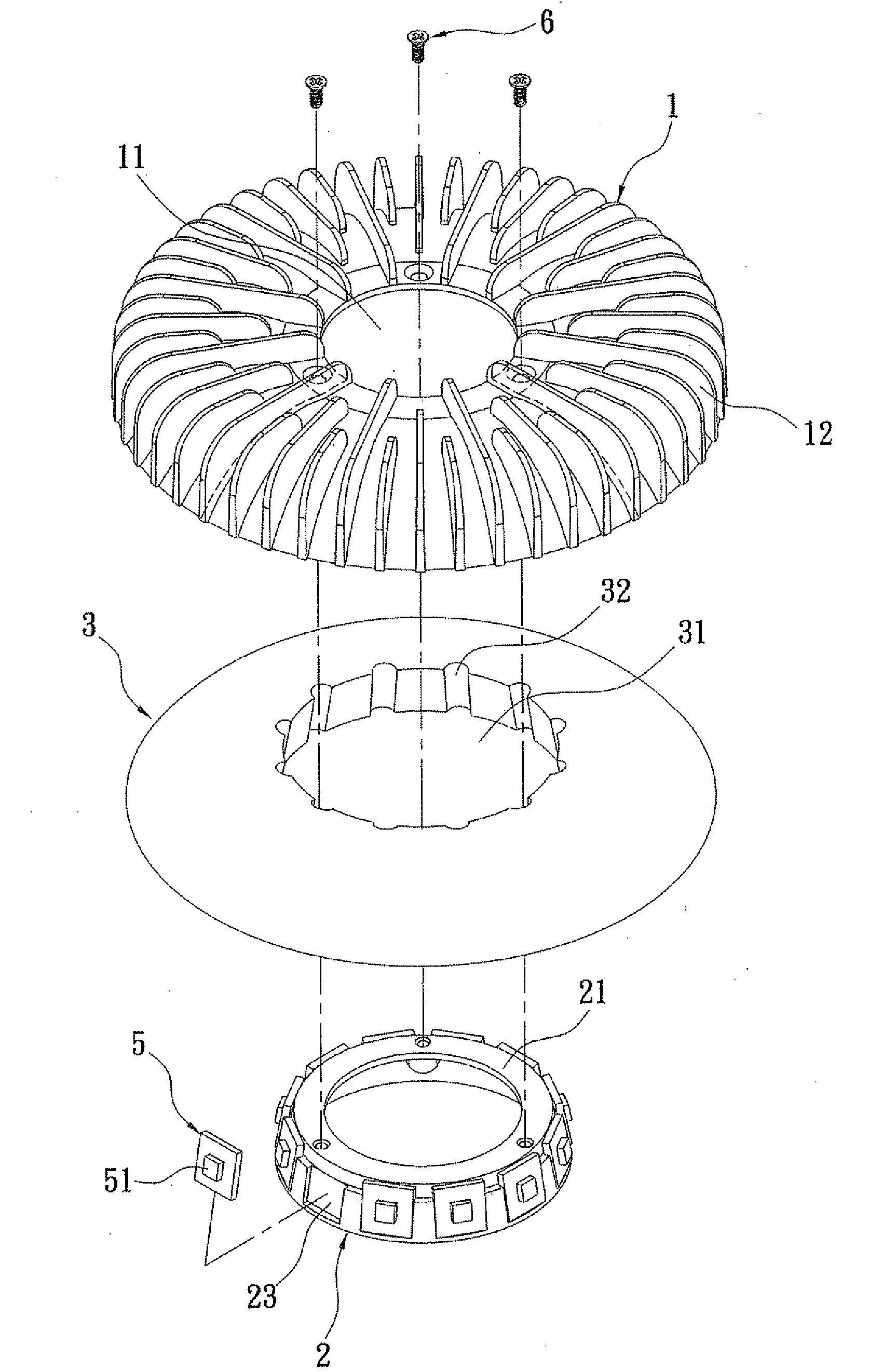
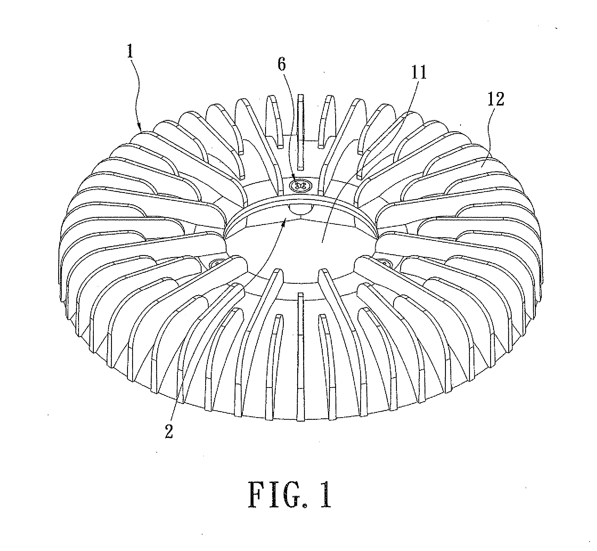
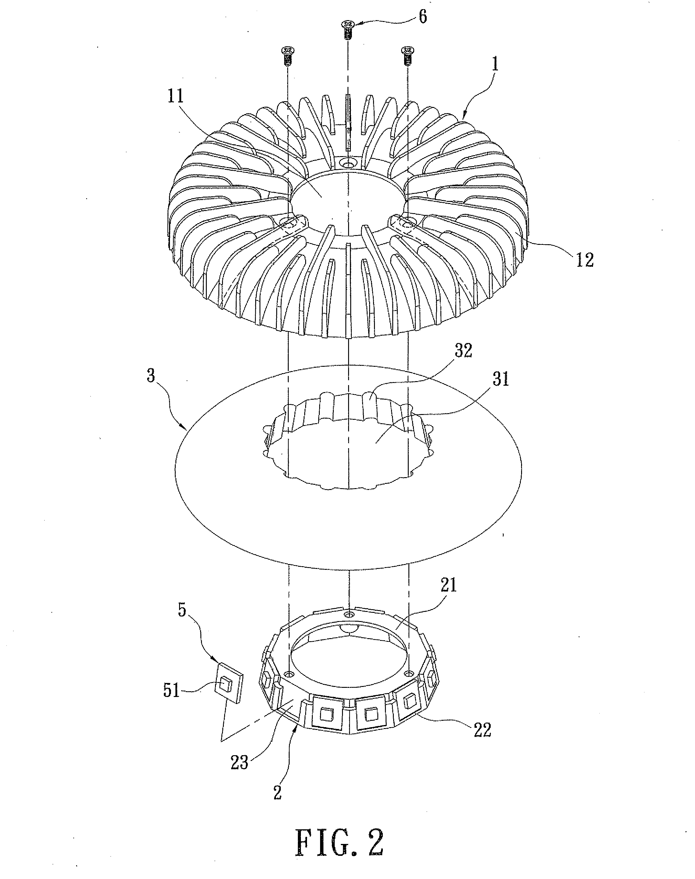
[0018]Please refer to FIGS. 1 to 4. The present invention discloses a lamp which includes a lampshade 1, a seat 2, a light-guiding element 3, a reflecting layer 4, and a plurality of circuit boards 5. In this embodiment, the lampshade 1 is made of aluminum, but the lampshade 1 can be made of other metals of good heat dissipating ability. The lampshade 1 is shaped like a bowl. The center of the lampshade 1 has a first opening 11 penetrating the lampshade 1 from top to bottom. A plurality of heat dissipating pieces 12 of different size is set around the outside of the lampshade 1. The plurality of heat dissipating pieces 12 extends from the first opening 11 to the edge of the lampshade 1.

[0019]In this embodiment, the seat 2 is made of aluminum, but it can be made of other metals of good heat dissipating ability. The seat 2 with a cylindrical shape is a polygon with multilateral side surfaces (see FIG. 2). A connecting part 21 is extended inwardly from the top edge of the seat 2. The c...


PUM


Abstract

The present invention disclosed a lamp, which includes a lampshade, a seat, a light-guiding element, a reflecting layer, and a plurality of circuit boards. The seat shows a cylindrical shape. The seat is installed in the lampshade. The light-guiding element corresponding to the seat is for light mixing. The light-guiding element is installed between the lampshade and the seat. The reflecting layer is disposed between the lampshade and the light-guiding element. Each of the circuit boards has a LED thereon. The circuit boards are installed on the seat. As a result, the light area becomes broad via the reflecting layer and then the light is overlapped in the light-guiding element to achieve the light-mixing effect. Thereby, the light transform from point to plane.

Description

BACKGROUND OF THE INVENTION[0001]1. Field of the Invention[0002]The present invention relates to a lamp and more particular to an improved lamp applying LEDs for increasing brightness.[0003]2. Description of Related Art[0004]Traditional Tungsten lamps produces light source that scatters, therefore ensures a certain degree of brightness to the surrounding area, however traditional tungsten lamps has the disadvantage of low electricity conversion into light, thus, there is now a growing trend of replacing the traditional tungsten lamps with light emitting diodes (LEDs).[0005]However, light emitted by LEDs is straight and not scattered, i.e. the light can only be focused on particular points. Thus, the brightness in locations outside of the lamp's light beam may be insufficient.[0006]According to the above, an improvement proposed. For example, the Taiwan patent number M317545 (publication date: 2007.08.21) discloses a lamp having LED, which includes a circuit board, LED, and reflectin...

Claims


Application Information

Patent Timeline
IPC IPC(8): F21V1/00
CPCF21V7/0008F21V7/0091F21V13/04F21V29/004F21V29/89G02B6/0018F21V29/505F21V29/75F21V29/77F21Y2101/02F21Y2115/10F21Y2103/33F21V5/00
Inventor CHEN, CHE-YEN
Owner GINGKO LIGHTING
Learn More