Temperature compensated current measuring device and battery pack using the same

a technology of temperature compensation and measuring device, which is applied in the direction of electric devices, thermoelectric instruments, instruments, etc., can solve the problems of inaccurate measurement of actual current flowing in the external resistor, ineffective control of charging/discharging batteries, etc., and achieve the effect of accurately measuring actual current flowing in a circui

Active Publication Date: 2009-04-02
SAMSUNG SDI CO LTD
View PDF6 Cites 49 Cited by
  • Summary
  • Abstract
  • Description
  • Claims
  • Application Information

AI Technical Summary

Benefits of technology

[0011]Aspects of the present invention are conceived to solve the above-described and/or other problems in the conventional art and thus an aspect of th

Problems solved by technology

However, when the measurement scope of the voltage value is extremely broad, the actual current flowing in the external

Method used


Image

  • Temperature compensated current measuring device and battery pack using the same
  • Temperature compensated current measuring device and battery pack using the same
  • Temperature compensated current measuring device and battery pack using the same

Examples


Embodiment Construction

[0028]Reference will now be made in detail to the present embodiments of the present invention, examples of which are illustrated in the accompanying drawings, wherein like reference numerals refer to the like elements throughout. The embodiments are described below in order to explain the present invention by referring to the figures.

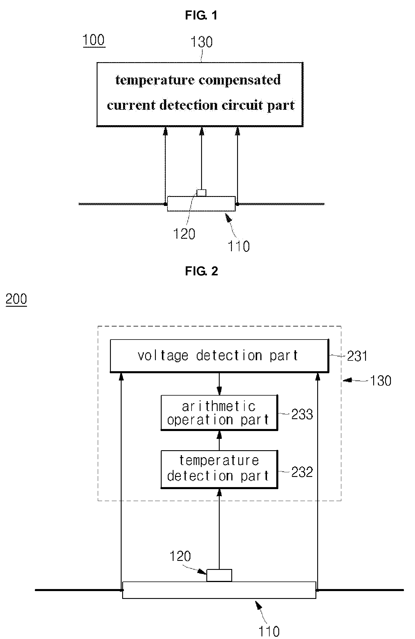
[0029]FIG. 1 is a circuit diagram of a temperature compensated current measuring device according to an embodiment of the present invention.

[0030]Referring to FIG. 1, the temperature compensated current measuring device 100 according to an embodiment of the present invention may include a conductor 110, a temperature sensor 120, and a temperature compensated current detection circuit part 130.

[0031]If current flows in the conductor 110, the conductor 110 can be used. For example, the conductor 110 may be formed as a pattern of a high-current path of a printed circuit pattern of a circuit board, or a conductive wire. When the conductor 110 is formed in ...


PUM


Abstract

A battery pack, and more particularly, a temperature compensated current measuring device which can accurately measure an actual current flowing in a circuit of a charging/discharging path in the battery pack. The temperature compensated current measuring device includes a conductor in which current flows, a temperature sensor disposed around the conductor to measure a temperature of the conductor, and a temperature compensated current detection circuit part electrically connected to two positions of the conductor to measure a voltage between the two positions, electrically connected to the temperature sensor to measure a temperature of the conductor, and measuring the current flowing in the conductor by using the measured temperature and the voltage as an input signal. Thus, it is possible to accurately calculate an actual charging/discharging current with the temperature compensated current measuring device and effectively control the charging capacity of the battery pack.

Description

CROSS-REFERENCE TO RELATED APPLICATION[0001]This application claims the benefit of Korean Application No. 2007-97982, filed Sep. 28, 2007, in the Korean Intellectual Property Office, the disclosure of which is incorporated herein by reference.BACKGROUND OF THE INVENTION[0002]1. Field of the Invention[0003]Aspects of the present invention relate to a battery pack, and more particularly, to a temperature compensated current measuring device which can measure current flowing in a conductor, and a battery pack using the same.[0004]2. Description of the Related Art[0005]Generally, a secondary battery can be rechargeable and thus repeatedly usable, which is different from a primary battery. The secondary battery is generally used as the main power of portable devices for communication, information processing, and audio / video. Currently, interests in the secondary battery are being increased and the development of the secondary battery is also being rapidly performed. The main reason there...

Claims


Application Information

Patent Timeline
IPC IPC(8): H01M10/48G01R1/44G01R19/32
CPCG01R1/203G01R19/32G01R1/44G01R31/382G01R31/374
Inventor SIM, SESUB
Owner SAMSUNG SDI CO LTD
Why Eureka
Try Eureka