Head-of-wall fireblock systems and related wall assemblies

a head-of-wall and fireblock technology, applied in the direction of walls, building components, structural elements, etc., can solve the problems of reducing or preventing the seriousness of the head-of-wall joint, and the inability to meet the needs of the user

Active Publication Date: 2009-04-09
CEMCO LLC
View PDF63 Cites 95 Cited by
  • Summary
  • Abstract
  • Description
  • Claims
  • Application Information

AI Technical Summary

Problems solved by technology

Head-of-wall joints often present a serious challenge in terms of reducing or preventing the spread of smoke and fire during a building fire.
All of these approaches, however, are relatively labor intensive and thus e

Method used


Image

  • Head-of-wall fireblock systems and related wall assemblies
  • Head-of-wall fireblock systems and related wall assemblies
  • Head-of-wall fireblock systems and related wall assemblies

Examples


example 1

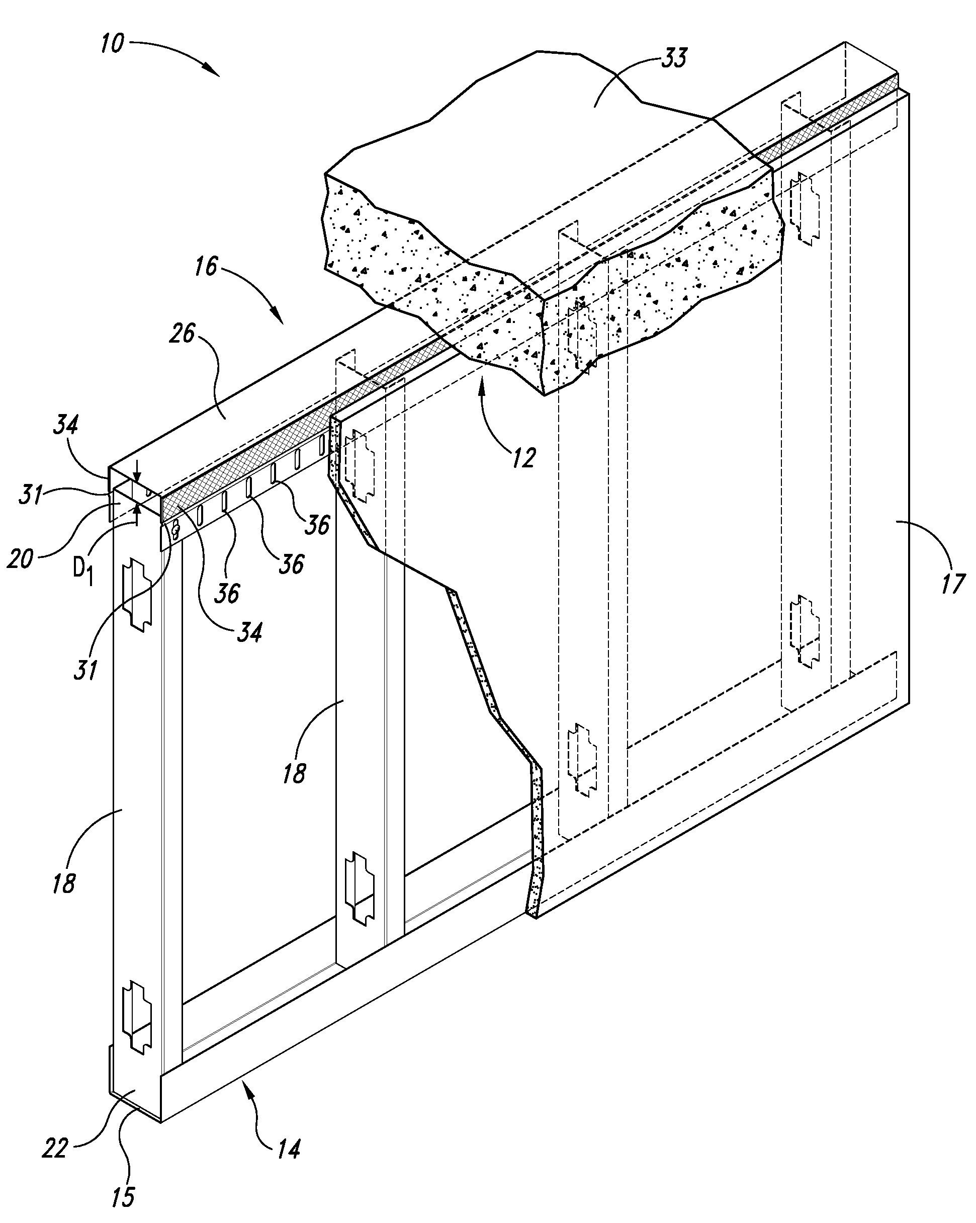
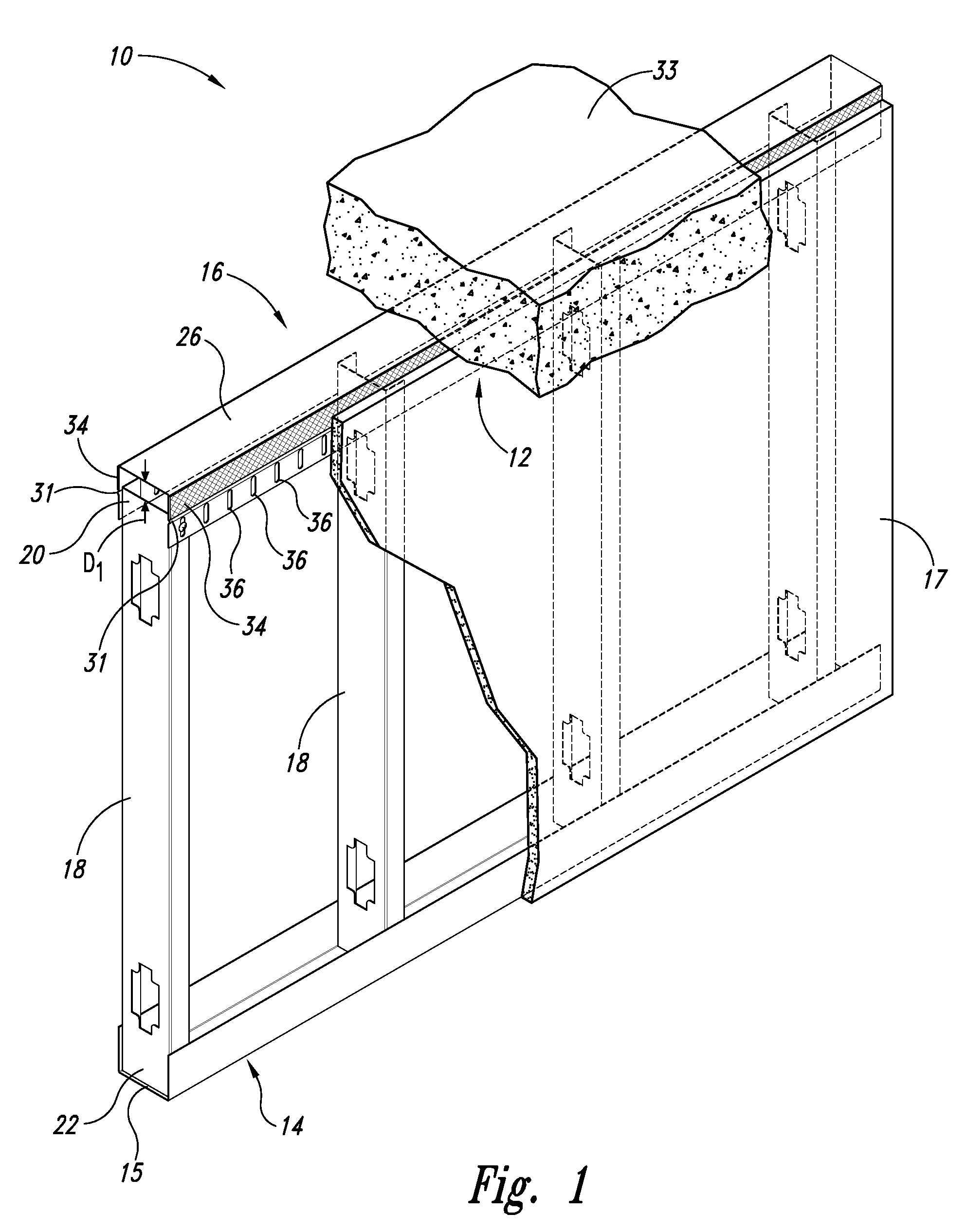
[0026]Several mock-ups of a fire retardant head-of-wall assembly in accordance with the present invention were constructed and tested to evaluate the joint system's resistance to a heat source followed by a hose stream in accordance with Underwriters Laboratories, Inc.'s standards set forth in its Tests for Fire Resistance of Building Joint Systems—UL 2079. Each mock-up was constructed so as to have a ⅜ inch head-of-wall linear construction gap, and the construction gap was cycled over this distance (translating to a maximum of a ¾ inch gap when the ceiling was upwardly deflected a maximum distance of ⅜ inch, and to a minimum of no gap when the ceiling was downwardly deflected a maximum distance of ⅜ inch) in order to demonstrate that the head-of-wall assembly was able to withstand (meaning without failure of any of the wall assembly components) various levels of cycling. More specifically, the several mock-ups successfully passed cycling Levels I, II, and III (with Level I=1 cycle / ...


PUM


Abstract

The invention disclosed herein is directed to a fire retardant head-of-wall assembly configured to seal a linear head-of-wall construction joint or gap when exposed to a heat source such as a building fire. The inventive fire retardant head-of-wall assembly comprises a header track having an elongated intumescent strip affixed lengthwise on at least one of the outer sidewall surfaces of the header track and above a centrally located and outwardly protruding lengthwise corrugated groove. When exposed to a heat source such as a building fire, the intumescent strip is able to expand so as to at least partially fill the head-of-wall construction joint or gap; and in so doing, retard or prevent the spread of smoke and fire. The inventive fire retardant head-of-wall assembly has been certified as complaint with respect to Underwriters Laboratories, Inc.'s standards set forth in its Tests for Fire Resistance of Building Joint Systems—UL 2079.

Description

CROSS-REFERENCE TO RELATED APPLICATIONS[0001]This Application claims the benefit of U.S. Provisional Application No. 60 / 997,521 filed on Oct. 4, 2007, and U.S. Provisional Application No. 61 / 007,439 filed on Dec. 13, 2007, which applications are incorporated herein by reference in their entireties for all purposes.TECHNICAL FIELD[0002]The present invention relates generally to fire blocking and containment systems used in the construction of buildings and, more particularly, to fireblocks and fire blocking systems used to seal dynamic head-of-wall construction joints and gaps.BACKGROUND OF THE INVENTION[0003]Metal framing assemblies used to construct commercial and residential buildings are common in the building construction arts. These metal framing assemblies are generally constructed from a plurality of metal framing members including studs, joists, trusses, and other metal posts and beams formed from sheet metal and frequently fabricated to have the same general cross-sectional...

Claims


Application Information

Patent Timeline
IPC IPC(8): E04C2/08
CPCE04B2/7457E04B2/7411
Inventor KLEIN, JAMES ALAN
Owner CEMCO LLC
Why Eureka
Try Eureka