Hydraulic Drive Device

a technology of hydraulic drive and drive device, which is applied in the direction of positive displacement liquid engine, gearing, fluid coupling, etc., can solve the problems of high manufacturing cost and complex piping structure, and achieve the effect of reducing the number of parts, reducing the size of the system, and reducing manufacturing cos

Inactive Publication Date: 2009-04-09
NIHON KENKI CO LTD
View PDF7 Cites 3 Cited by
  • Summary
  • Abstract
  • Description
  • Claims
  • Application Information

AI Technical Summary

Benefits of technology

[0028]The present invention can decrease the number of parts and can reduce the manufacturing cost compared with the conventional art, because it has the construction that the first variable-displacement hydraulic motor and second variable-displacement hydraulic motor are arranged inside the combination of front casing and rear casing. Further, the first variable-displacement hydraulic motor and second variable-displacement hydraulic motor can be arranged close to each other, thereby making it possible to realize a reduction in the size of the system. In addition, the piping that guide oil to be supplied to and drained from the first variable-displacement hydraulic motor and second variable-displacement hydraulic motor can be formed as oilways in the rear casing, so that the piping structure can be simplified compared with the conventional technology.

Problems solved by technology

As the first variable-displacement hydraulic motor 8 and second variable-displacement hydraulic motor 11 have the front casings and rear casings to form their main bodies, respectively, the above-described conventional technology requires a large number of parts and hence tends to result in high manufacturing cost.
Moreover, piping associated with the respective hydraulic motors 8,11 are required so that the piping structure tends to become complex.

Method used


Image

  • Hydraulic Drive Device
  • Hydraulic Drive Device
  • Hydraulic Drive Device

Examples


first embodiment

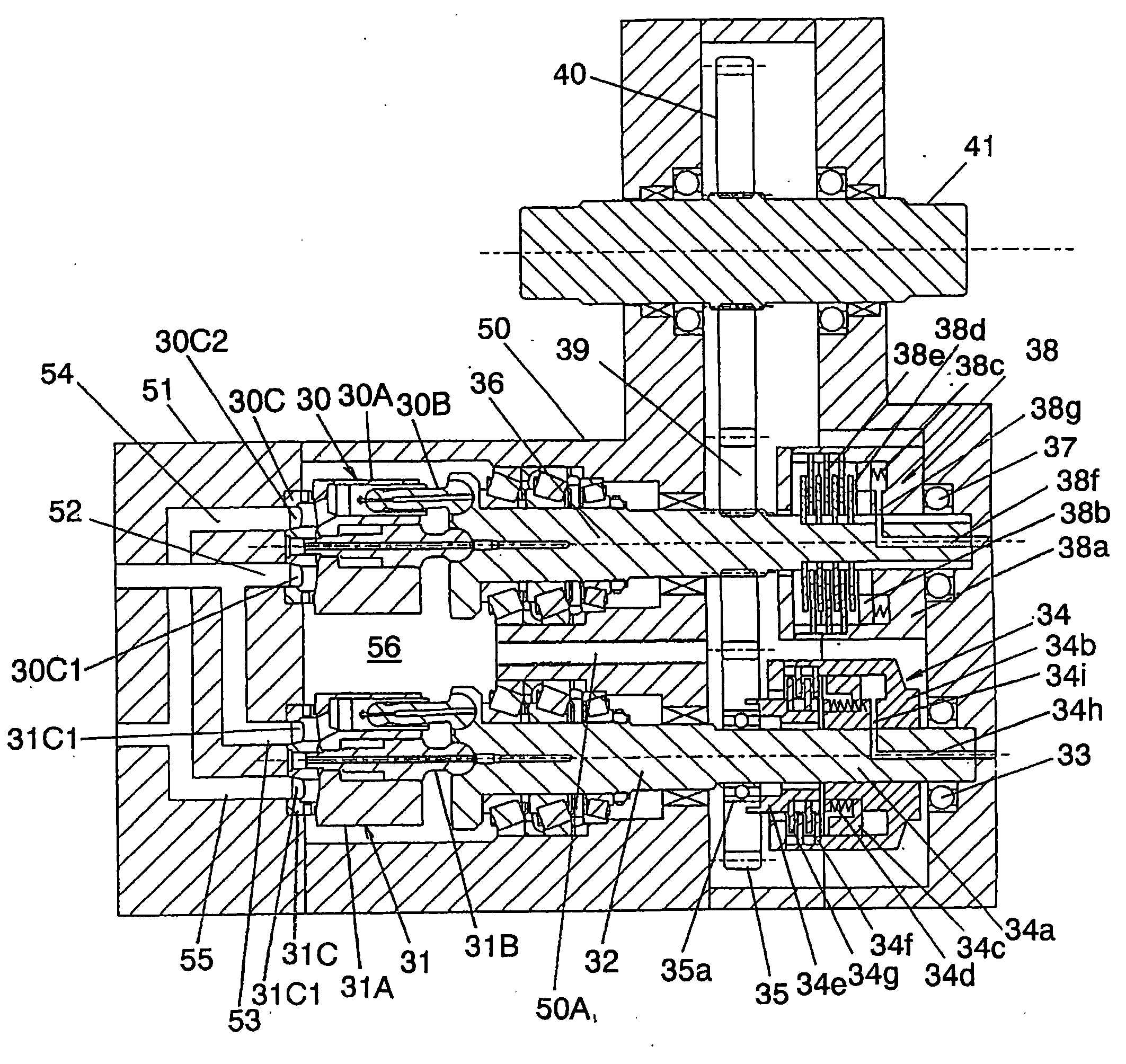
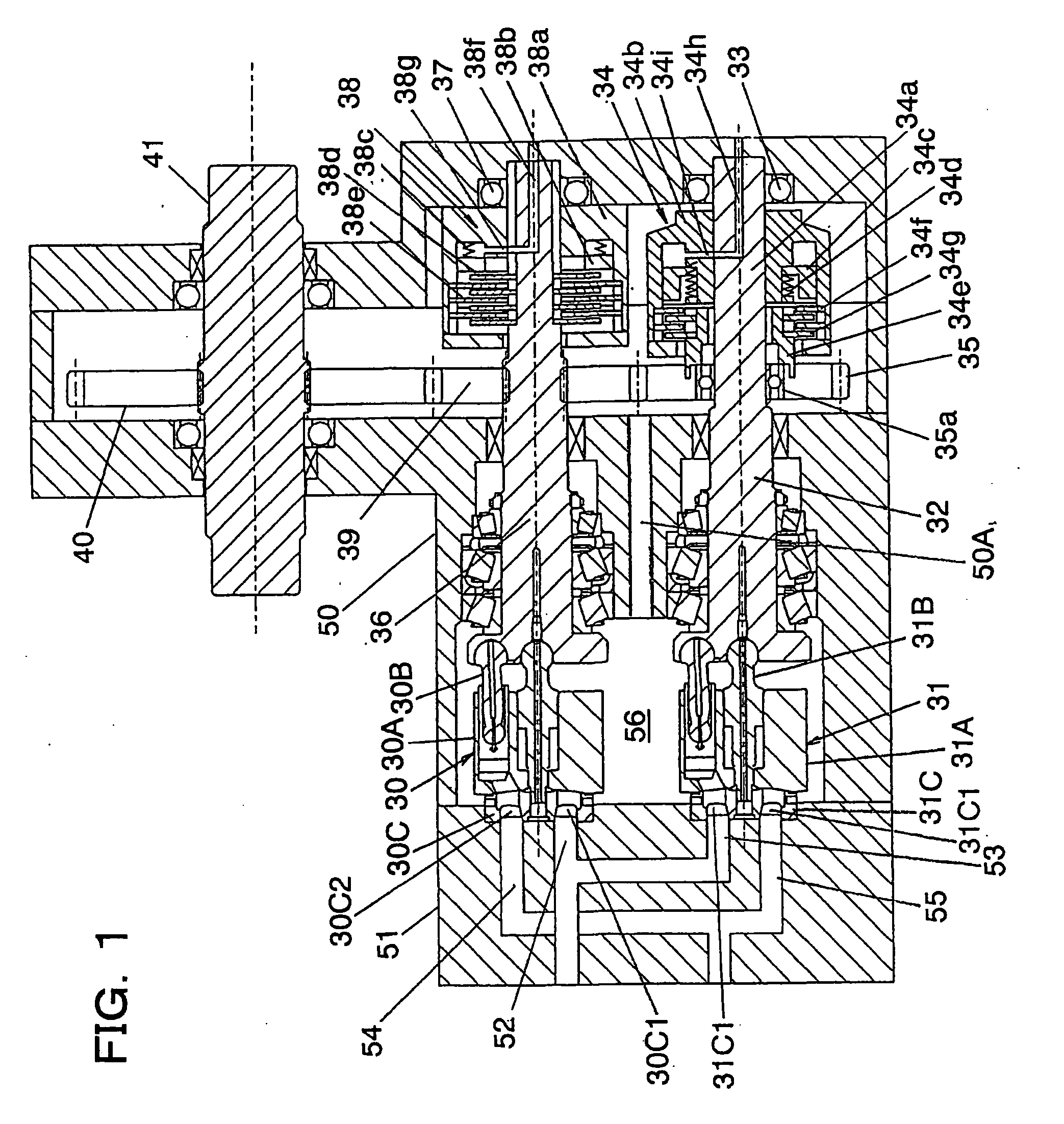
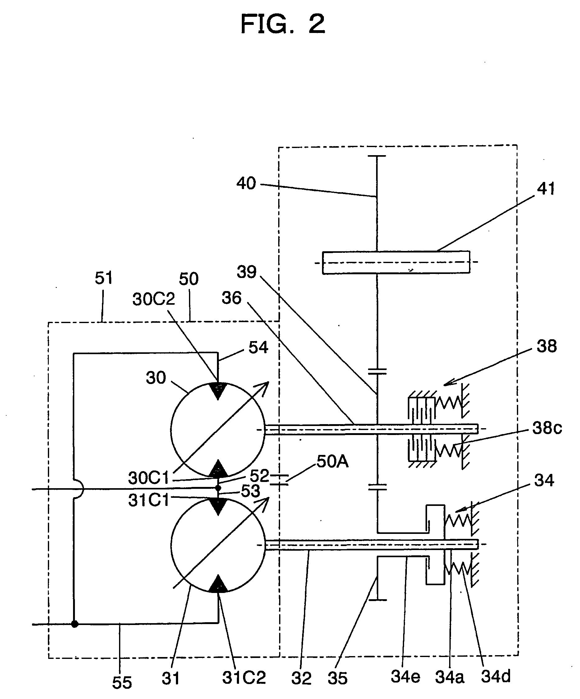
[0037]The clutch unit 34 which can transmit the output of the second variable-displacement hydraulic motor 31 to the final output shaft 41 includes a clutch drive shaft 34a and a clutch driven shaft 34e. The clutch drive shaft 34a is arranged on an output shaft 32 of the second variabledisplacement hydraulic motor 31, and rotates integrally with the output shaft 32, while the clutch driven shaft 34e is arranged for selective connection with or disconnection from the clutch drive shaft 34a and, when connected, transmits the output of the second variable-displacement hydraulic motor 31 to the final output shaft 41. In this first embodiment, the output shaft 32 of the second variable-displacement hydraulic motor 31 and the clutch drive shaft 34a of the clutch unit 34 are constructed of the same member. Described specifically, the clutch drive shaft 34a of the clutch unit 34 is formed on an extension of the output shaft 32 of the second variable-displacement hydraulic motor 31.

[0038]As ...

second embodiment

[0062]The second embodiment is also provided with a gear 34e1, which is included in the transmission means that transmits the output of the second variable-displacement hydraulic motor 31 to the final output shaft 41 and which rotates integrally with the clutch driven shaft 34e. A bearing is arranged between the gear 34e1 and the output shaft 36 of the first variable-displacement hydraulic motor 30. Owing to the arrangement of this bearing, the rotation of the output shaft 36 of the first variable-displacement hydraulic motor 30 is not transmitted to the gear 34e1.

[0063]These gears 35,34e1,39,40 are arranged such that the gear 35 fixed on the output shaft 32 of the second variable-displacement hydraulic motor 31 and the above-described gear 34e1 rotatable integrally with the clutch driven shaft 34e are maintained in meshing engagement with each other and that, for example, the gear 39 fixed on the output shaft 36 of the first variable-displacement hydraulic motor 30 and the gear 40 ...


PUM


Abstract

A hydraulic drive system is provided with a front casing 50 and a rear ceasing 51. The front casing 50 is formed of a single member, and accommodates therein rotary members, which include a cylinder block 30A and the like, and a part of an output shaft 36 of a hydraulic motor 30 and rotary members, which include a cylinder block 31A and the like, and a part of an output shaft 32 of a hydraulic motor 31. The rear casing 51 is joined to the front casing 50, and has a ports plate 30C and a ports plate 31C arranged therein. The rear casing 51 has an oilway 52 communicating to a first port 30C1 of the ports plate 30C, an oilway 53 communicating to the oilway 52 and also communicating to a first port 31C1 of the ports plate 31C, an oilway 54 communicating to a second port 30C2 of the ports plate 30C, and an oilway 55 communicating to the oilway 54 and also communicating to a second port 31C2 of the ports plate 31C.

Description

TECHNICAL FIELD[0001]This invention relates to a hydraulic drive system to be arranged on a construction machine or the like having a running function, such as a wheel loader.BACKGROUND ART[0002]As a conventional technology of this kind, there is the technology disclosed in Patent Document 1. FIG. 5 is a skeleton diagram of a conventional hydraulic drive system, and FIG. 6 is a cross-sectional view illustrating a clutch unit which a second variable-displacement hydraulic motor in the conventional hydraulic drive system is provided with.[0003]As illustrated in FIG. 5, a first variable-displacement hydraulic motor 8 which is a high-speed low-torque motor is connected to a final output shaft 2 via an output shaft 5, a gear 4 and a gear 3. On the other hand, a second variable-displacement hydraulic motor 11 which is a low-speed high-torque motor is connected to the final output shaft 2 via an output shaft 26, a clutch unit 10, a gear 6, the gear 4 and the gear 3.[0004]As depicted in FIG...

Claims


Application Information

Patent Timeline
Patent Type & Authority Applications(United States)
IPC IPC(8): F15B15/00
CPCF04B23/06F16H2047/025F16H2039/005F16H47/02
Inventor YABUUCHI, YOSHITOMOSUGIYAMA, GENROKUKOBAYASHI, TAKESHINIIDOME, TAKASHIKURIHARA, TAKESHI
Owner NIHON KENKI CO LTD
Why Eureka
Try Eureka