
Shock simulation generator

a generator and simulation technology, applied in the field of shock simulation generators, can solve the problems of crashing into the water, causing rotational and athwartship forces, and shocking the target,

Active Publication Date: 2009-04-09
HUNTINGTON INGALLS
View PDF5 Cites 17 Cited by
  • Summary
  • Abstract
  • Description
  • Claims
  • Application Information

AI Technical Summary

Benefits of technology

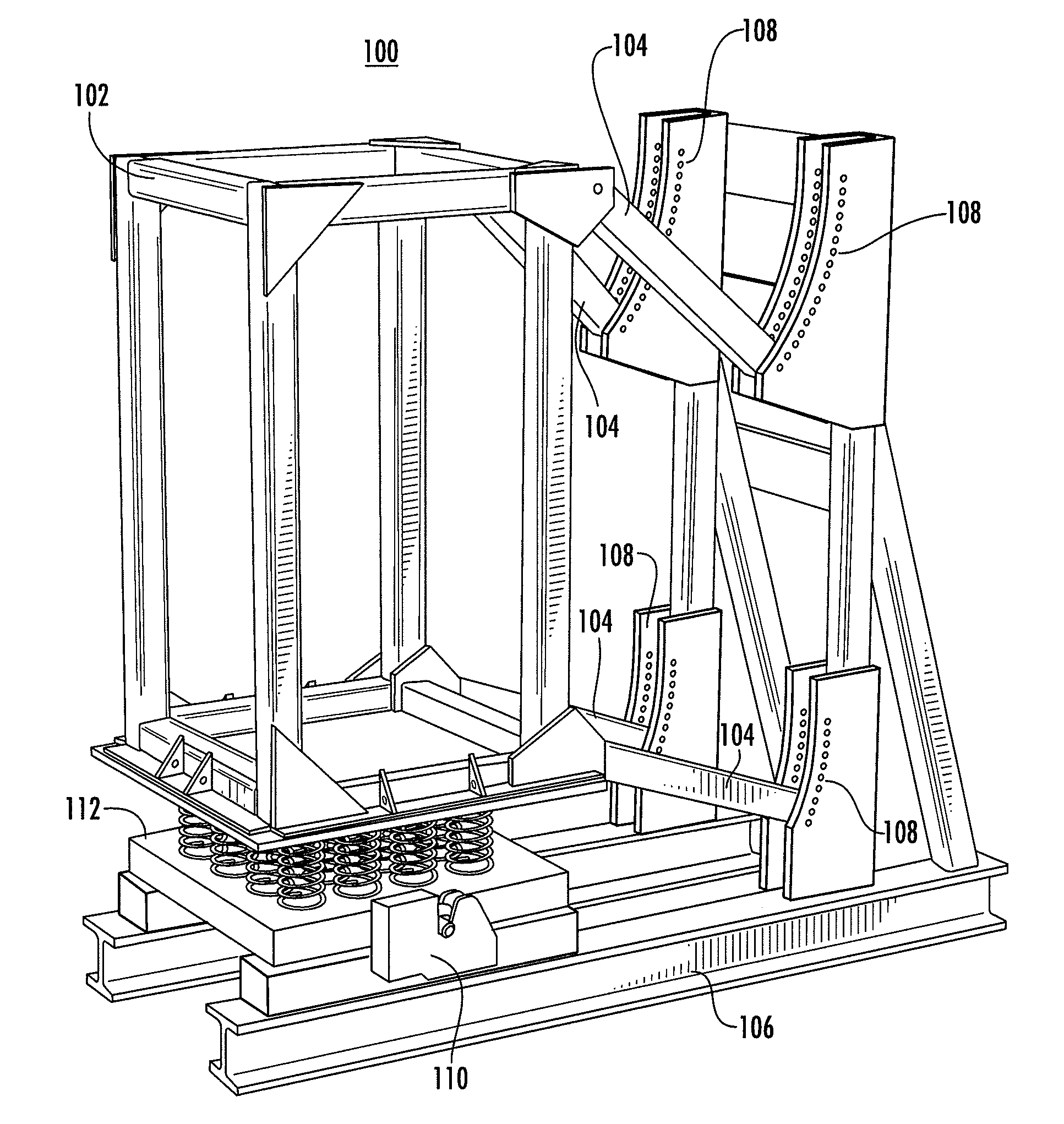
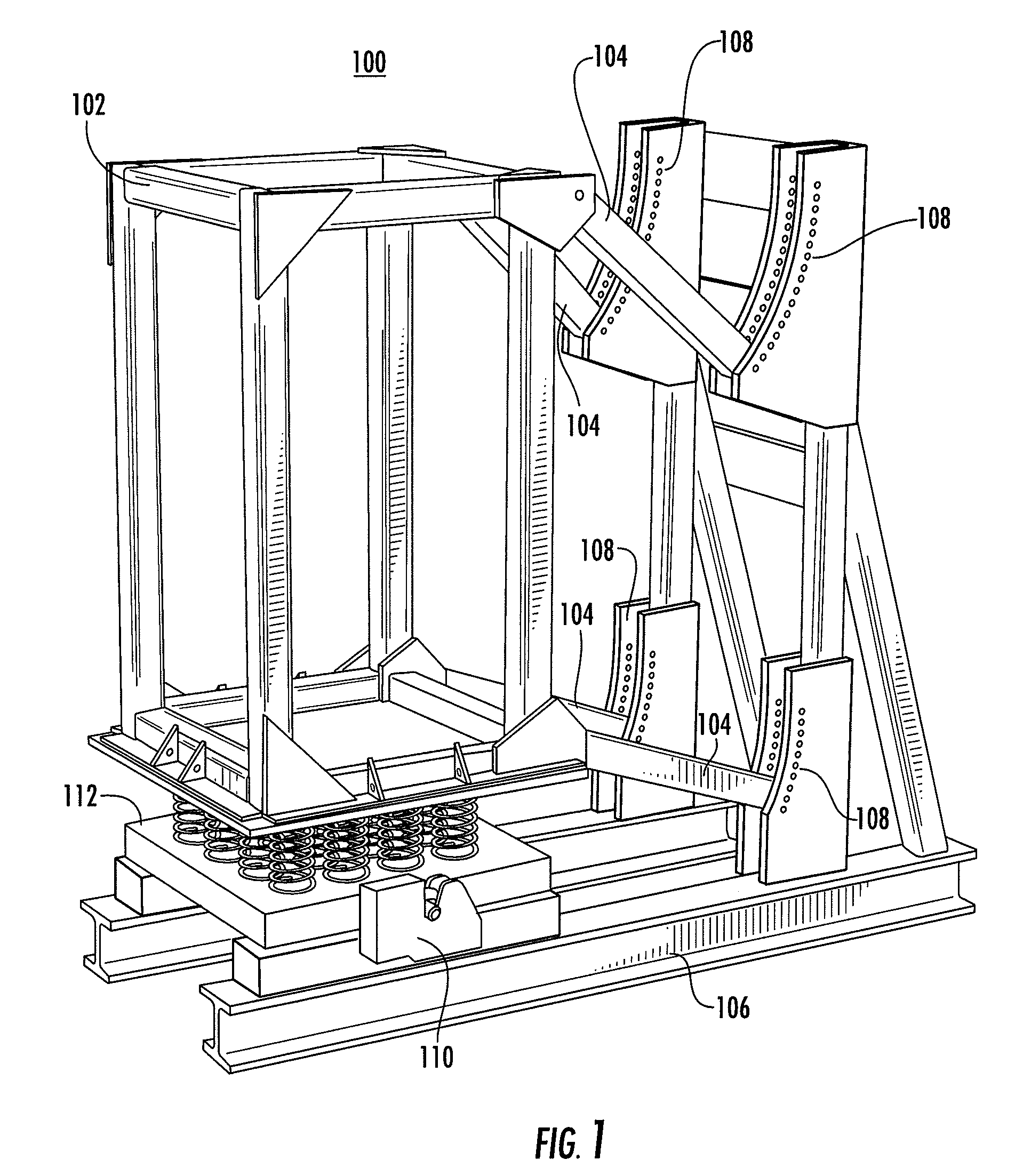
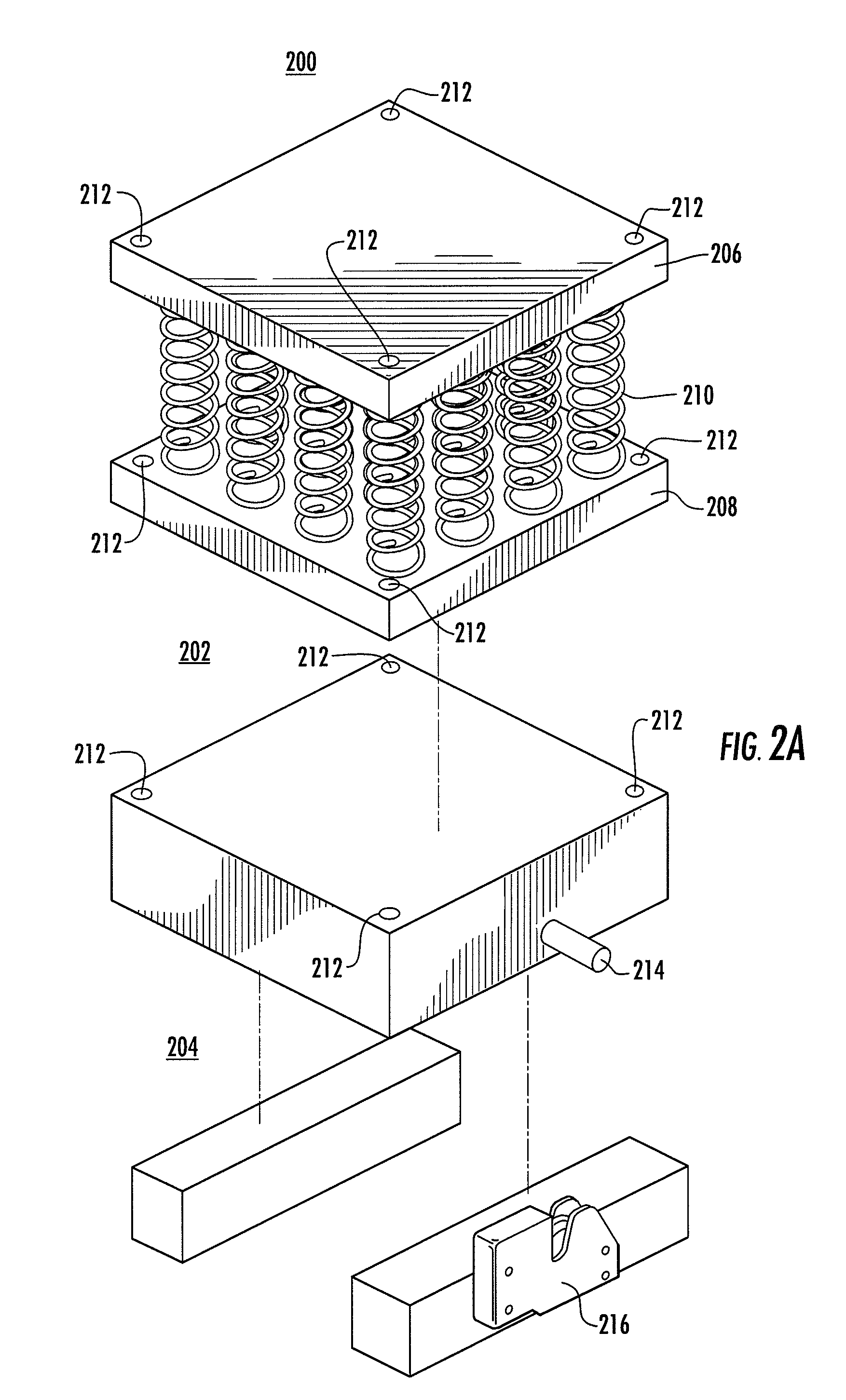
[0013]To prevent any unwanted rebounding response and to direct the shock energy at the target, the shock generation system can also include a locking assembly that quickly couples the cage to the foundation at impact. For example, the locking assembly can include two rotating forks that are integrated into the foundation and two locking pins in the resonation simulator. When the resonation simulator slams into the foundation, the locking pins enter the rotating forks, which prevent the cage from bouncing up. In other embodiments, the locking pin(s) or the locking assembly can be integrated into the cage, and / or an entirely different type of locking assembly can be used by the shock generation system.

Problems solved by technology

The subsequent explosion creates a wave of energy and an air bubble, both of which can shock the target.
An explosion directed at the side of a surface ship, for example, is likely to also cause the ship to rock side to side, thereby creating rotational and athwartship forces, while many of its components (such as its deck) reverberate at a specific frequency from the shock waves.
If the explosion is great enough, the wave of energy can even blast a hole through the hull and / or the bubble can physically lift the hull of the boat out of the water, only to have it crash down into the water and break.
Regardless of whether the hull withstands the initial shock wave and bubble, each reverberation can create its own mini-shock that can causes damage to equipment and injury to people on the boat.
In addition, the reverberations can act collectively at a given frequency and cause even more damage.
Eventually, the energy of the shock waves dissipates and can no longer be felt.
Shock tests in many ways are controlled chaos, especially the heavy weight, high explosive tests that are currently conducted.
Accordingly, a single target or type of target may have to be tested a number of times. Each explosive shock test can cost tens of thousands of dollars, but such tests are required nonetheless by the U.S. military.

Method used


Image

  • Shock simulation generator
  • Shock simulation generator
  • Shock simulation generator

Examples


Embodiment Construction

[0022]Traditional shock tests, which may use advanced pyrotechnics in remote regions of the country, can currently cost tens of thousands of dollars. In addition to the expensive materials used to blow-up the targets, engineers often spend hours, even weeks, preparing for a single set of explosive shock tests. Among other things, engineers must calculate the explosive force, angle, and direction used to create the shock. The engineers must also take into consideration the shock waves produced by the initial shock and under water bubble.

[0023]But even before the explosive test can be conducted, the target must be physically shipped to the test location. Simply getting a piece of sensitive military equipment to a remote test site can also be expensive. U.S. Navy ships, for example, are often built near the ocean, which are generally the most heavily populated locations in the country. Such populated locations often restrict the types of explosions that may be employed to conduct an ex...


PUM

PropertyMeasurementUnit
massaaaaaaaaaa
weightaaaaaaaaaa
mass ratioaaaaaaaaaa

Abstract

This is directed to systems, methods, computer programs and other means for shock testing a piece of equipment, i.e., the target. The target can be mounted to a shock generation machine, which is then slammed into a sturdy foundation. The impact can result in multi-axis loads, depending on how the machine is configured, while also simulating the modal frequency response of an object, such as a naval ship's deck.

Description

CROSS-REFERENCE TO RELATED APPLICATIONS[0001]This application is related to and claims the benefit of U.S. Provisional Patent Application No. 60 / 978,433 (“the '433 Prov. App.”), filed Oct. 9, 2007, which is incorporated herein by reference in its entirety.TECHNICAL FIELD[0002]This relates to systems, methods and other means for generating shocks. In some embodiments, the shocks simulate a sudden and violent blow or impact that a component may experience on a naval warship or other platform.BACKGROUND OF THE INVENTION[0003]The United States military currently requires vigorous testing for any piece of equipment that is intended for battle. In some instances, even the components of some equipment, such as mission critical equipment, must be individually tested.[0004]Shock testing is one type of testing used by the military and military contractors. Shock testing is meant to simulate an attack, such as an explosion from a bomb, torpedo or missile that occurs in close proximity to the d...

Claims


Application Information

Patent Timeline
Patent Type & Authority Applications(United States)
IPC IPC(8): G01N3/303
CPCG01N3/303
Inventor TALLEY, MICHAEL A.PIZZANO, CHARLES L.DAVIS, CARLA J.HARN, JONATHAN R.
Owner HUNTINGTON INGALLS
Learn More