Cylinder pressure sensor system

a sensor system and cylinder technology, applied in the field of sensor systems, can solve problems such as undesirable approaches of engine manufacturers

Inactive Publication Date: 2009-04-09
DELPHI TECH INC
View PDF14 Cites 42 Cited by
  • Summary
  • Abstract
  • Description
  • Claims
  • Application Information

AI Technical Summary

Benefits of technology

[0006]The present invention is directed to an improved approach for packaging a cylinder pressure sensor. The invention has the advantage of eliminating the need to provide a separate port in the engine whose sole purpose would be to install a cylinder pressure sensor.

Problems solved by technology

However, this approach is considered undesirable by engine manufacturers.

Method used


Image

  • Cylinder pressure sensor system
  • Cylinder pressure sensor system
  • Cylinder pressure sensor system

Examples


Embodiment Construction

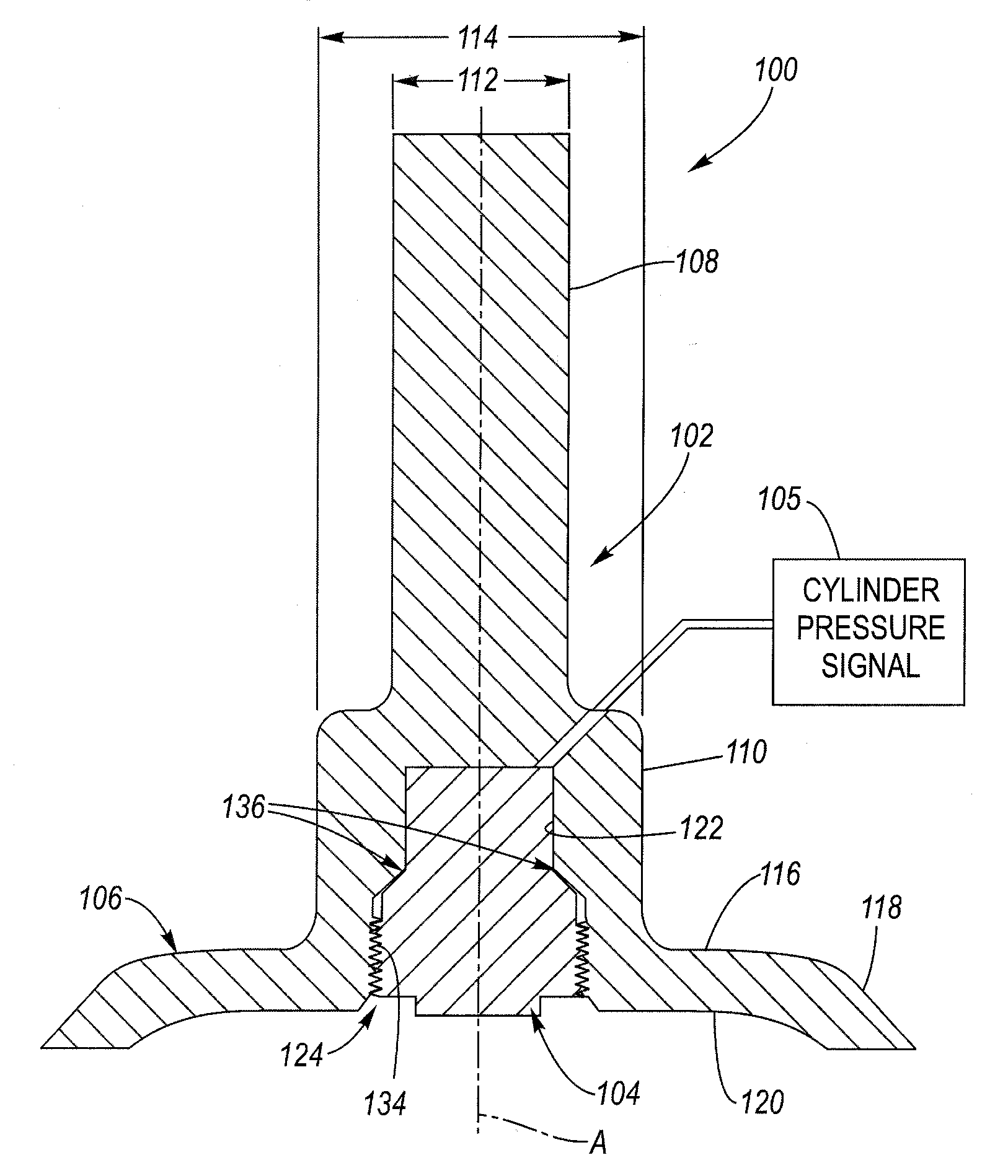
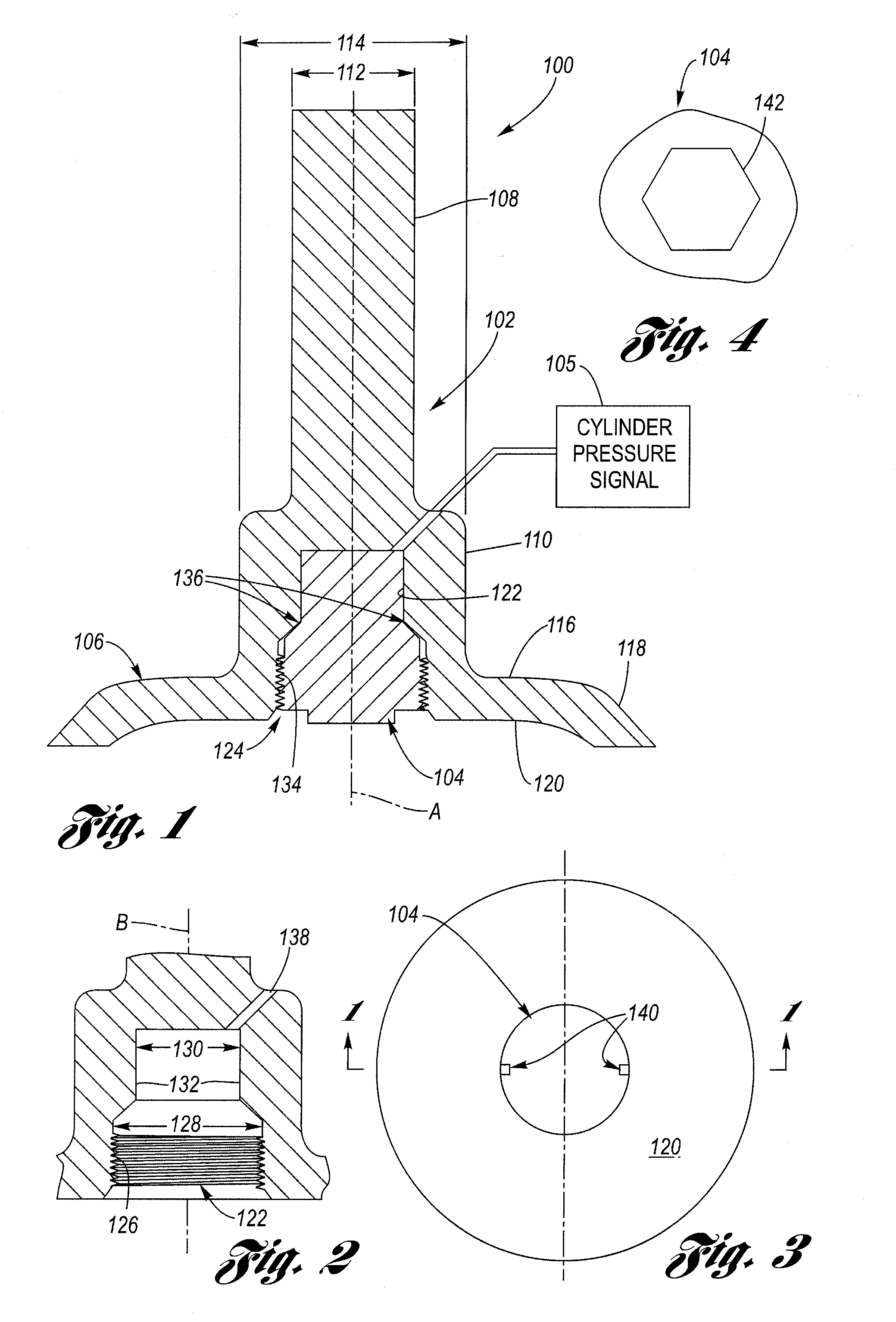
[0016]Referring now to the drawings wherein like reference numerals are used to identify identical components in the various views, FIG. 1 is a cross-sectional view of an assembled cylinder pressure sensor system 100 according to the present invention. Sensor system 100 includes an engine valve, such as an intake valve 102 and a cylinder pressure sensor 104. The present invention provides generally for the improved packaging of sensor 104 completely within valve 102 so as to allow for the normal, as-designed-for operation of the valve itself. That is, the invention does not call for materially altering the proper functioning of the valve so it will not in turn materially affect the combustion process in the cylinder. The combination valve / sensor system 100, in addition to its conventional valve function, is configured to generate a pressure signal 105 that is indicative of a sensed pressure within a combustion chamber or cylinder of the engine. The valve 102, in general terms, compr...


PUM

PropertyMeasurementUnit
pressureaaaaaaaaaa
diameteraaaaaaaaaa
combustion pressureaaaaaaaaaa

Abstract

An engine intake valve has a threaded blind bore opening from its top surface facing the engine cylinder. A pressure sensor has a body portion whose exterior is threaded and is configured in size and shape to be completely received within and retained in the blind bore. The pressure sensor is configured to generate a pressure signal indicative of the cylinder pressure.

Description

TECHNICAL FIELD[0001]This invention relates generally to sensor systems, and more particularly, to a cylinder pressure sensor system for sensing a pressure in a cylinder of an internal combustion engine.BACKGROUND OF THE INVENTION[0002]In the automotive industry, among others, it is known to employ ever-increasingly sophisticated engine management techniques for the control of an internal combustion engine. This is due to the desire to improve fuel economy as well as reduce emissions and / or comply with emissions standards. In this regard, one type of control sensor desirable for use is a pressure sensor to detect the pressure in the combustion chamber (i.e., cylinder), which information may be used as feedback for adjusting fuel delivery and spark timing parameters, among other uses. Other known uses for combustion pressure information include exhaust gas recirculation (EGR) control and combustion knock detection.[0003]One approach known in the art for implementing cylinder pressure...

Claims


Application Information

Patent Timeline
Patent Type & Authority Applications(United States)
IPC IPC(8): G01L9/00
CPCG01L23/222
Inventor VILLAIRE, WILLIAM L.
Owner DELPHI TECH INC
Why Eureka
Try Eureka