Mounting device

a technology of mounting device and skimmer, which is applied in the direction of machine supports, special-purpose vessels, vessel construction, etc., can solve the problems of inability to use the fin at a low relative speed of water and at a stop, the cabin, seat and floor of the vessel are kept inclined in unfavorable attitudes,

Inactive Publication Date: 2009-04-09
MAEDA TERUO
View PDF5 Cites 6 Cited by
  • Summary
  • Abstract
  • Description
  • Claims
  • Application Information

AI Technical Summary

Benefits of technology

[0009]According to a first aspect of the present invention there is provided a mounting device including a base, a movable body for mounting at least one of a passenger and a cargo, a supporting mechanism disposed between the base and the movable body, and a controller for controlling the supporting mechanism. The supporting mechanism is capable of applying supporting forces to the movable body from a plurality of positions of the base to support the movable body on the base and determining a center of oscillation of the movable body so t

Problems solved by technology

They are, however, unavailable at a low relative speed of water and at a stop thereof.
In addition, applications of the fins are limited to the vehicles moving in or on fluid, for example, the ships and the airplanes.
These conventional ships, seat device and floor structure described

Method used


Image

  • Mounting device
  • Mounting device
  • Mounting device

Examples


first embodiment

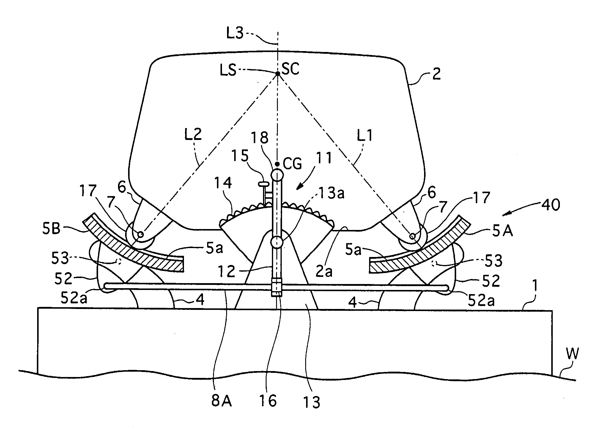
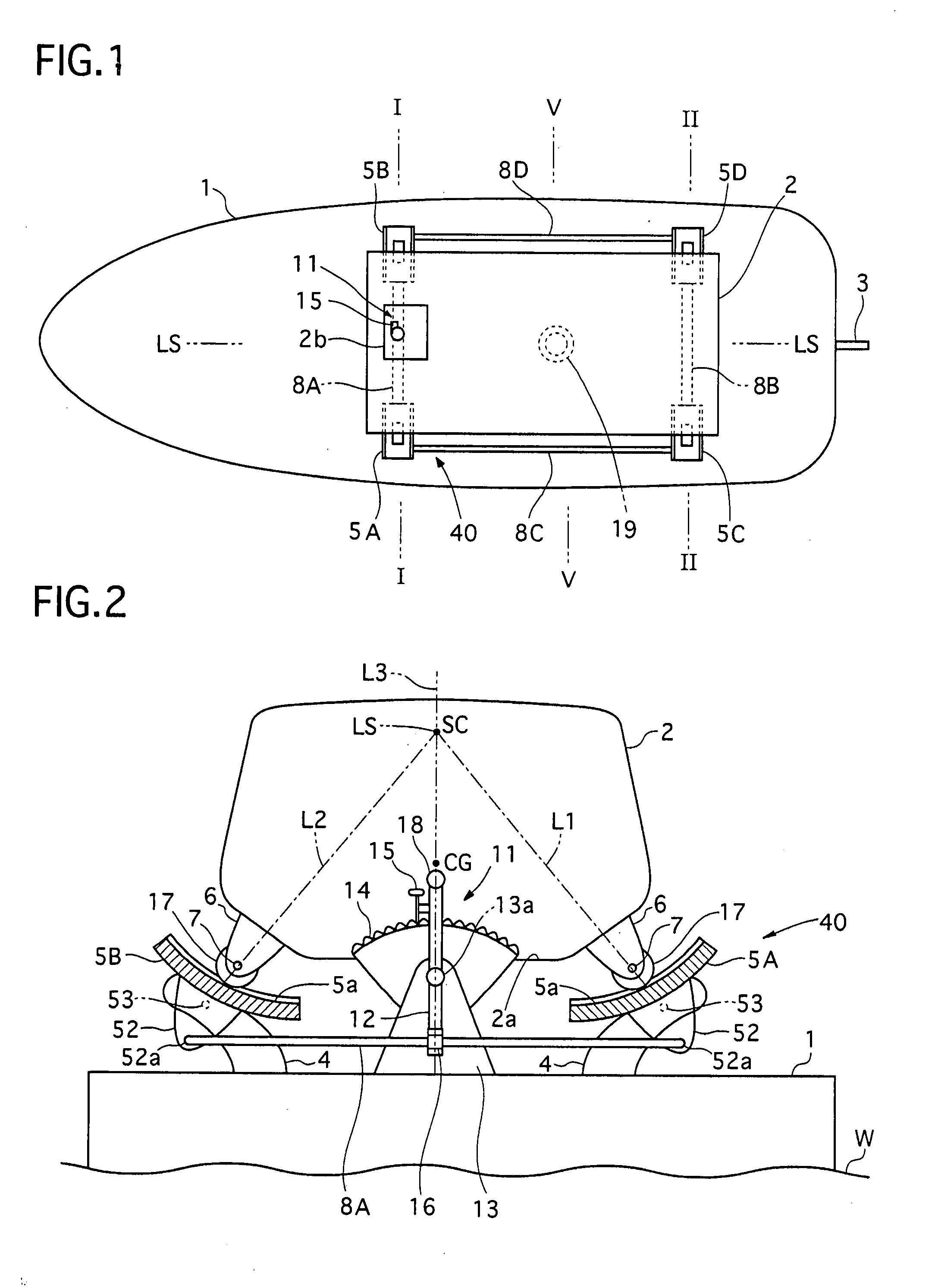
[0025]Referring to FIGS. 1 and 2 of the drawings, there is shown a first preferred embodiment of a mounting device according to the present invention. In the first embodiment, the mounting device is applied to a water vehicle such as a boat and a ship for keeping a floor for a passenger and / or a cargo to be substantially horizontal in a plane of a rolling motion thereof.

[0026]The water vehicle includes a hull 1, a cabin 2, and a supporting mechanism 40 disposed between the hull 1 and the cabin 2. The hull 1 corresponds to a base of the present invention, and the cabin 2 corresponds to a movable body of the present invention.

[0027]The hull 1 is equipped with a rudder 3 at its rear portion, and mechanically and supports the cabin 2 at its intermediate portion by the supporting mechanism 40. The supporting mechanism 40 keeps the cabin 2 as possible in this embodiment in a state where the hull 1 and the cabin 2 are swingable relative to each other.

[0028]The cabin 2 is provided with a fl...

second embodiment

[0061]Next, a mounting device of a second embodiment according to the invention will be described with reference to the accompanying drawing.

[0062]Referring to FIG. 7, there is shown the second preferred embodiment of the mounting device, which is also applied to a water vehicle. In the second embodiment, a hull 1 and a cabin 2 are swingable relative to each other in both of a rolling motion direction and a pitching motion direction.

[0063]The mounting device includes the hull 1, the cabin 2 with a flat floor therein, and a supporting mechanism 50 disposed between the hull 1 and the cabin 2.

[0064]The hull 1 and the cabin 2 are constructed similarly to those of the first embodiment, although the hull 1 is partially illustrated and the cabin 2 is more schematically illustrated by alternate long and two short dashes lines in FIG. 7.

[0065]The supporting mechanism 50 has a rectangular frame 55, a first supporting mechanism 51 disposed between the hull 1 and the rectangular frame 55, and a...

third embodiment

[0075]Next, a mounting device of a third embodiment according to the invention will be described with reference to the accompanying drawing.

[0076]Referring to FIG. 8, there is shown the third preferred embodiment of the mounting device, which is also applied to a water vehicle. In the third embodiment, a hull and a cabin are also swingable relative to each other in both of a rolling motion direction and a pitching motion direction as well as the second embodiment.

[0077]The hull and the cabin are constructed similarly to those of the first and second embodiments, although the hull and the cabin are not illustrated in FIG. 8. A supporting mechanism 60 is disposed between the hull and the cabin, and has a first supporting mechanism, a second supporting mechanism and a rectangular frame 55 disposed therebetween.

[0078]The first supporting mechanism is, although not illustrated in FIG. 8, constructed similarly to that of the second embodiment so as to shift the front and rear centers of o...


PUM


Abstract

A mounting device including a base, a movable body, a supporting mechanism disposed therebetween, and a controller for controlling the mechanism. The mechanism applies supporting force to the movable body from a plurality of positions of the base to support the movable body on the base and determines a center of oscillation of the movable body with respect to the center of oscillation which is higher than the center of gravity of the movable body. The controller controls the mechanism to shift the center of oscillation, by changing directions support forces, at least in a horizontal direction according to a change of the center of the oscillation so that a change in an inclination of the mounting device due to a load transfer to the movable body can be decreased.

Description

BACKGROUND OF THE INVENTION[0001]1. Field of the Invention[0002]The present invention relates to a mounting device including a base and a movable body for mounting a passenger, a cargo or the like thereon, the base supporting the movable body so that a change in an inclination of the movable body due to a load shift thereof can be decreased.[0003]2. Description of the Related Art[0004]In some mounting devices such as water vehicles, efforts have been made to provide ride comfort and / or carrying stability of cargoes by keeping floors in a horizontal direction. Such conventional ships are disclosed in Japanese patents laid-open publication No. (Hei) 6-286687 and No. (Hei) 6-166396. These conventional ships are equipped with a plurality of fins which are provided at a right side and a left side of a hull thereof. The fins are independently controlled to change their angles of attack so as to suppress a rolling motion, a pitching motion and the like of the hull. They are, however, unava...

Claims


Application Information

Patent Timeline
IPC IPC(8): F16M11/18B63B17/00B64C1/00
CPCB63B29/12
Inventor MAEDA, TERUO
Owner MAEDA TERUO
Why Eureka
Try Eureka