Downhole Load Sharing Motor Assembly

a technology of motor assembly and downhole, applied in the field of motors, can solve the problems of assembly still operating in a fairly inefficient manner, disproportionate wear on the master motor, and inability to meet the needs of the master motor,

Inactive Publication Date: 2009-04-09
SCHLUMBERGER TECH CORP
View PDF13 Cites 32 Cited by
  • Summary
  • Abstract
  • Description
  • Claims
  • Application Information

AI Technical Summary

Problems solved by technology

With separate motors, however, there is an inherent tendency for one motor to take on an increasing amount of load while the other starts to contribute less and less.
Unfortunately, as the load on the master-slave motor assembly increases, the response of the assembly is to initially elevate the torque output provided by the master motor until communication between the motors results in re-establishing the equilibrium as noted above.
Thus, when the motor assembly is initially turned on and upon any increase in load thereafter, there is an imbalance of load until equilibrium can be re-established.
As noted above, during this period of unbalanced load, the assembly still operates in a fairly inefficient manner and with disproportionate wear on the master motor.
Furthermore, the master motor, like any, may be unable to operate without stalling, overheating or other malfunctioning when directed to pull a load beyond its own inherent limitations.
Nevertheless, in a master-slave motor configuration as described, the likelihood that the master motor will be directed to exceed an operational load threshold is increased during the allowed periods of unbalanced load.
Unfortunately, this places a high performance criteria on the electronics of the assembly.
As such, an expensive, intricate and large bus communication may be utilized that is, nevertheless, susceptible to being overloaded during operation of the master-slave motor assembly.
Thus, even where efficiency is improved through a complex bus communications and relays, inherent efficiency limitations remain.
Furthermore, the employment of multiple motors to share a common load in the oilfield industry presents a particular challenge to downhole equipment such as the above noted tractor.
This makes use of conventional mechanical motors generally impractical.

Method used


Image

  • Downhole Load Sharing Motor Assembly
  • Downhole Load Sharing Motor Assembly
  • Downhole Load Sharing Motor Assembly

Examples


Embodiment Construction

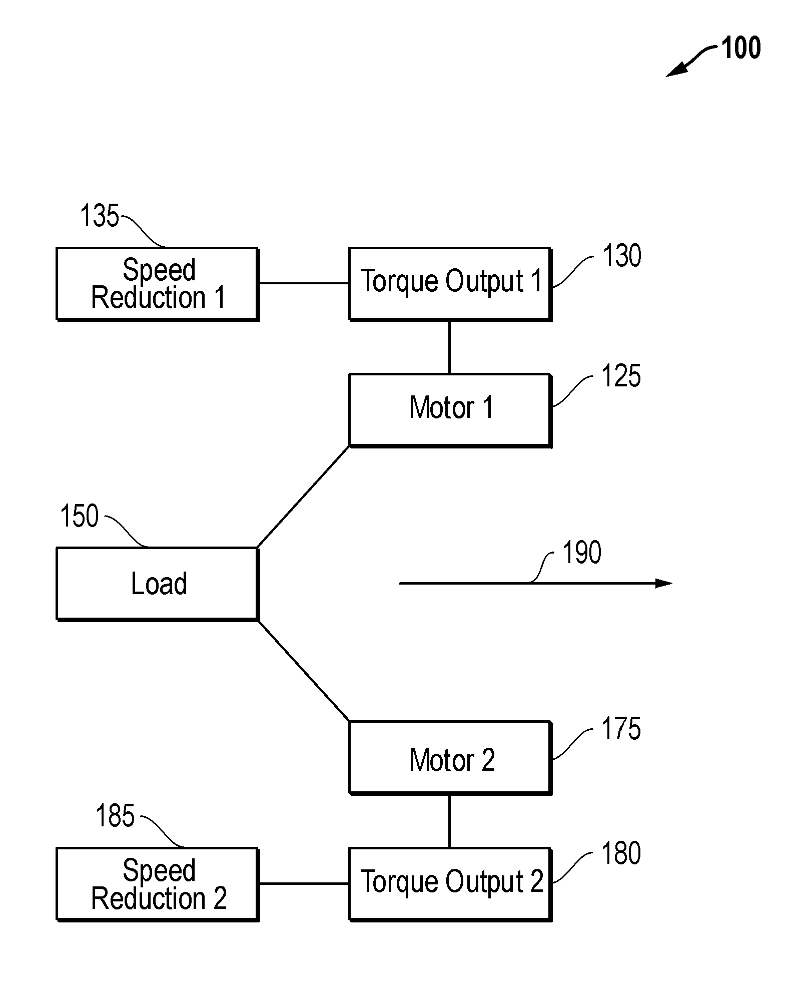
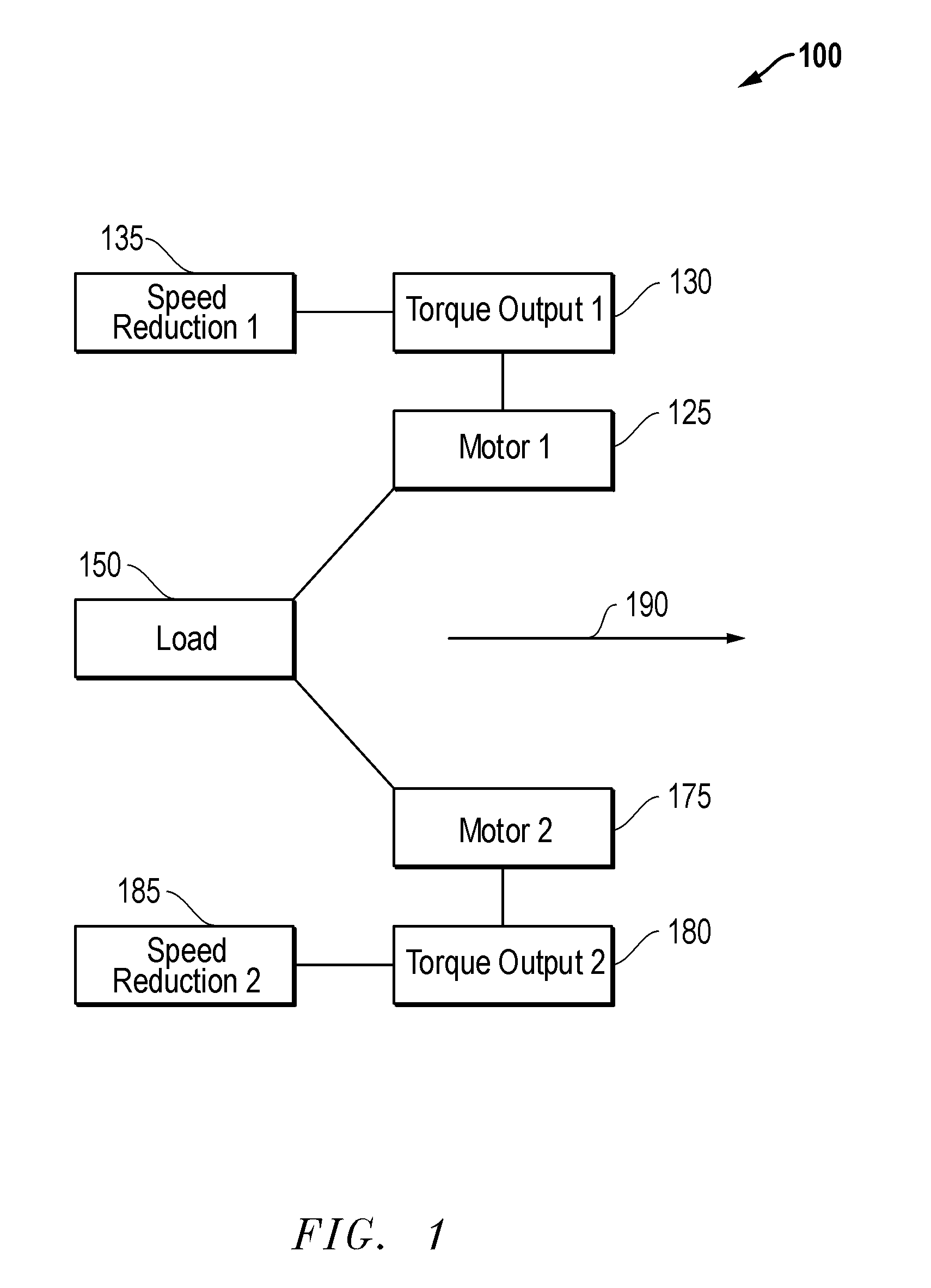
[0018]Embodiments are described with reference to certain downhole multiple motor assemblies which are configured to share a load. In particular, assemblies employing two permanent magnet synchronous machine (PMSM) motors are described. However, other types of motor assemblies may be employed with differing numbers of motors. For example, more than two motors may be employed with the assembly. Regardless, embodiments described herein may include assemblies with downhole PMSM motors, or other substantially constant adjustable speed motors configured to display substantial equilibrium in torque output during a downhole operation. Additionally, as used herein, the term “substantially constant adjustable speed motor” is meant to refer to a motor configured to operate at a substantially constant speed during operation such as a conventional PMSM, but which may also be actively directed to adjust its speed during operation.

[0019]Referring now to FIG. 1, a diagram of a downhole load sharin...


PUM


Abstract

A motor assembly of multiple motors for use in driving a shared downhole load within a well. In particular, the assembly may employ substantially constant adjustable speed motors. These may include permanent magnet synchronous machine motors. The motors may be configured to operate at given speeds that may be downwardly adjusted depending on the amount of torque output independently exhibited by the individual motors. In this manner, a significant divergence in torque output between the motors may be avoided so as to ensure substantial load sharing between all of the motors of the assembly.

Description

CROSS REFERENCE TO RELATED APPLICATION(S)[0001]This Patent Document is a continuation-in-part claiming priority under 35 U.S.C. §120 to U.S. application Ser. No. 11 / 854,370 entitled Electronic Motor, filed on Sep. 12, 2007, and incorporated herein by reference in its entirety. In addition, this Patent Document claims priority under 35 U.S.C. §119(e) to U.S. Provisional Application Ser. No. 60 / 998,687, entitled, Load Sharing Between Two Electric Motors, filed on Oct. 12, 2007, and incorporated herein by reference in its entirety.BACKGROUND[0002]Embodiments described relate to motors for driving a load downhole within a well. In particular, embodiments of load sharing motors in the form of a downhole power assembly are described. The motor assembly may be configured to dimensionally fit the downhole environment and to drive a load with enhanced sharing between the motors themselves.BACKGROUND OF THE RELATED ART[0003]Drilling, completing, and operating hydrocarbon wells involves the em...

Claims


Application Information

Patent Timeline
Patent Type & Authority Applications(United States)
IPC IPC(8): H02P6/04
CPCE21B4/04E21B4/16H02P5/46E21B43/128E21B4/18H02P5/00
Inventor MONTOIS, MICHAELSHEIRETOV, TODOR K.
Owner SCHLUMBERGER TECH CORP
Why Eureka
Try Eureka