Display device and transmitting device

a technology which is applied in the field of display device and transmitting device, can solve problems such as unfavorable user convenience, and achieve the effects of reducing cost, cost reduction, and cost reduction

Inactive Publication Date: 2009-04-09
SONY CORP
View PDF3 Cites 82 Cited by
  • Summary
  • Abstract
  • Description
  • Claims
  • Application Information

AI Technical Summary

Benefits of technology

[0032]In this way, the transmission path through which the video signal is received from the transmitting device to the display device is used also for transmitting the remote control signal from the display device to the transmitting device. Therefore, a connection between the transmitting device and the display device can be performed by only a single HDMI cable, for example, and thus, miniaturization and reduction in cost of the display device and the transmitting device can be implemented.
[0033]According to embodiments of the present invention, in a display device which receives a video signal from an external apparatus via a transmission path and displays an image, a communicating unit for performing, a bi-directional communication is used to transmit coordinate i

Problems solved by technology

For example, when a plurality of apparatuses, such as the television receiver, the personal computer,

Method used


Image

  • Display device and transmitting device
  • Display device and transmitting device
  • Display device and transmitting device

Examples


Embodiment Construction

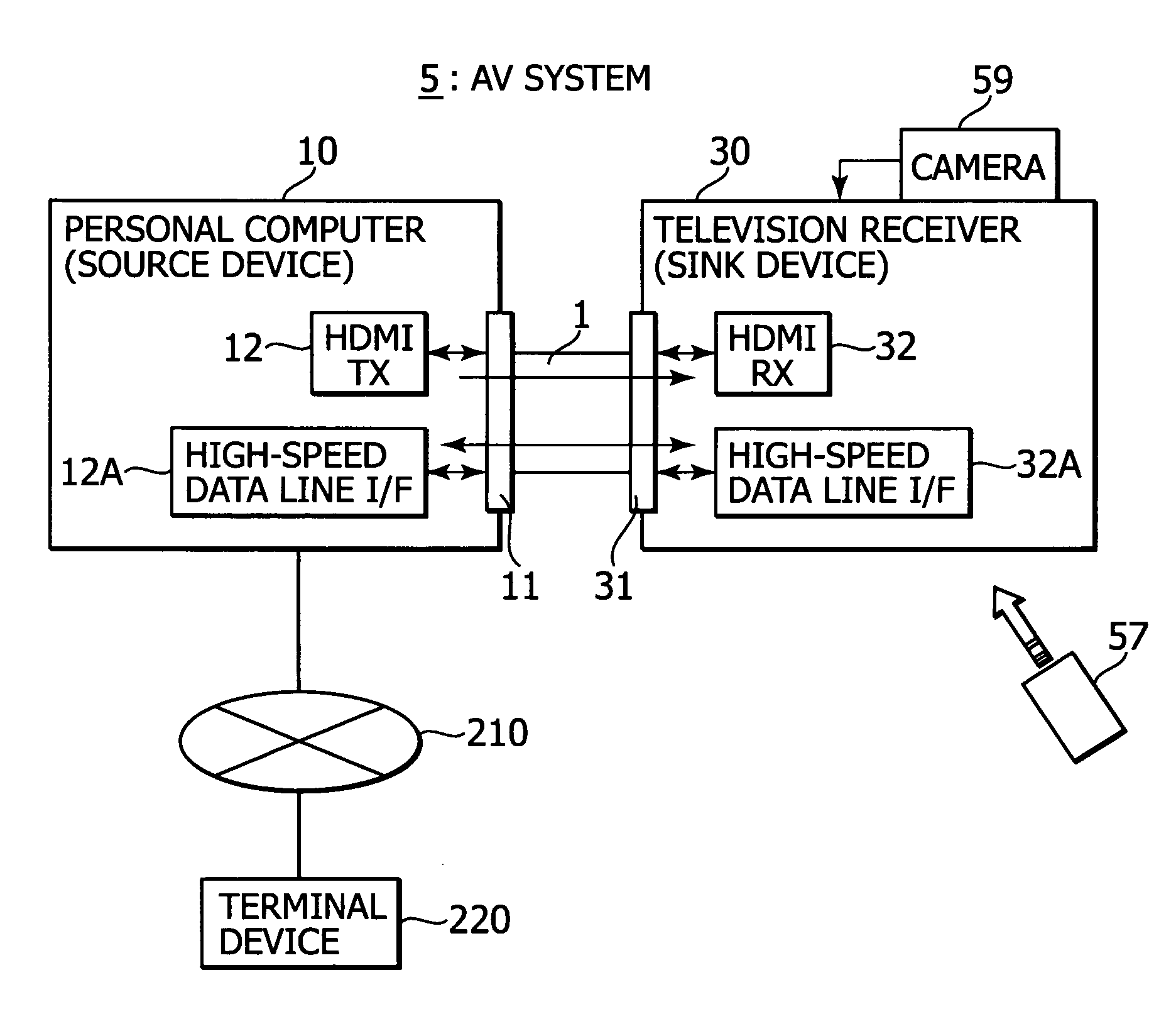
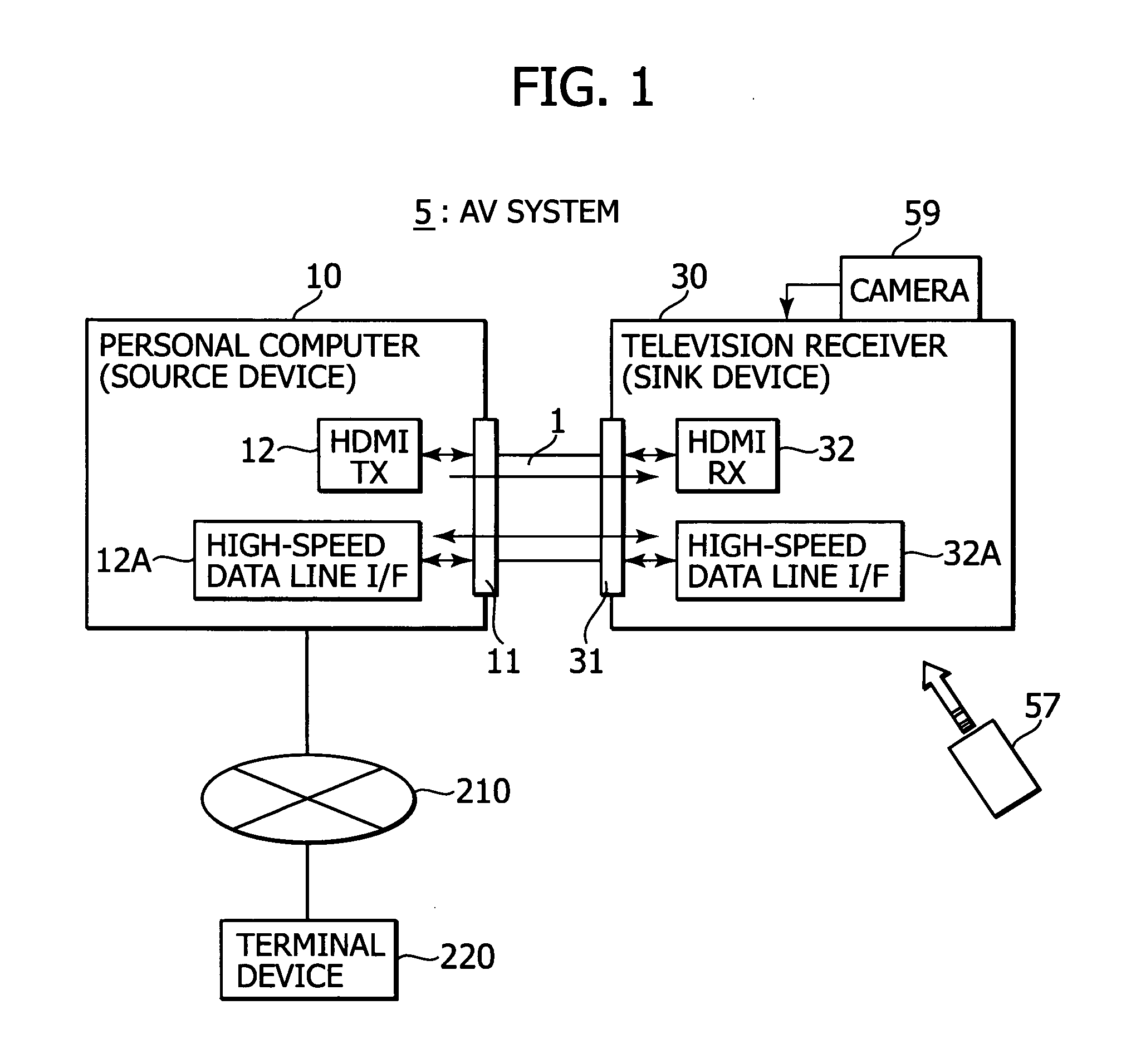
[0062]With reference to drawings, an embodiment of the present invention will be described below. FIG. 1 shows a configuration example of an AV (Audio Visual) system 5 as an embodiment.

[0063]The AV system 5 includes a personal computer (PC) 10 as a source device and a television receiver 30 as a sink device. The personal computer 10 and the television receiver 30 are connected via an HDMI cable 1.

[0064]The personal computer 10 is provided with an HDMI terminal 11 connected with an HDMI transmitting unit (HDMITX) 12 and a high-speed data line interface 12A. The television receiver 30 is provided with an HDMI terminal 31 connected with an HDMI receiving unit (HDMI RX) 32 and a high-speed data line interface 32A. One end of the HDMI cable 1 is connected to the HDMI terminal 11 of the personal computer 10, and the other end of the HDMI cable 1 is connected to the HDMI terminal 31 of the television receiver 30.

[0065]The personal computer 10 is connected to a terminal device 220 via a net...


PUM


Abstract

A display device includes a signal receiving unit, an image display unit, a communicating unit, a position designating unit, and an information transmitting unit. The signal receiving unit receives a video signal by a differential signal through a plurality of channels from an external apparatus via a transmission path. The image display unit processes the vide signal received in the signal receiving unit to display an image. The communicating unit performs a bi-directional communication by using a predetermined line which constitutes the transmission path. The position designating unit designates a position on a display screen of the image display unit. The information transmitting unit transmits, by the communicating unit, coordinate information on the position designated by the position designating unit to the external apparatus.

Description

CROSS-REFERENCE TO RELATED APPLICATIONS[0001]The present application claims benefit of priority of Japanese patent Application No. 2007-261609 filed in the Japanese Patent Office on Oct. 5, 2007, the entire disclosure of which is incorporated herein by reference.BACKGROUND OF THE INVENTION[0002]1. Field of the Invention[0003]The present invention relates to a display device and a transmitting device.[0004]2. Description of Related Art[0005]To configure an interactive system in which user input to a television receiver (TV) is sending to a personal computer (PC), there has been a need of using a plurality of cables: such as a cable for sending a video signal from the personal computer to the television receiver (for example, DVI, and VGA); a cable for sending an audio signal from the personal computer to the television receiver (an RCA cable, a stereo mini cable, etc.); and a cable for sending the user input into the television receiver to the personal computer (for example, USB, RS2...

Claims


Application Information

Patent Timeline
IPC IPC(8): H04N3/27H04N5/66H04N5/44G06F3/153G09G3/20H04N7/173
CPCG09G5/003H04L5/20G09G2370/047G09G2370/12H04N5/4403H04N5/765H04N5/775H04N9/8205H04N21/4113H04N21/4122H04N21/42204H04N21/44222H04N21/482H04N2005/443H04N5/38H04N21/43635H04L25/085G09G5/006H04N21/42224H04N21/44224
Inventor KITARU, KATSUNORINAKAJIMA, YASUHISA
Owner SONY CORP
Why Eureka
Try Eureka