
Optical pickup head and optical recording and replaying device

a technology of optical recording and optical recording, which is applied in the direction of optical recording heads, data recording, instruments, etc., can solve the problems of not being able to use a so-called three-beam method, the optical pickup head is not compatible, and the optical recording head is not compatibl

Inactive Publication Date: 2009-04-02
SAE MAGNETICS (HK) LTD
View PDF0 Cites 1 Cited by
  • Summary
  • Abstract
  • Description
  • Claims
  • Application Information

AI Technical Summary

Benefits of technology

The present invention provides an optical pickup head and an optical recording and replaying device that can play multiple types of optical discs. The optical pickup head has a semiconductor laser, a light receiving element, and an object lens unit with two different numerical apertures that can be moved in a tangential direction or a radial direction of the disc-shaped recording medium. This allows for the selection of the appropriate object lens for each type of recording medium, resulting in a simplified optical path and reduced costs. The optical pickup head and the optical recording and replaying device can be miniaturized and have low cost and light weight. The use of a plurality of object lenses at different positions on the disc is avoided, which simplifies tracking error detection methods.

Problems solved by technology

These optical pickup heads have not been compatible.
As a result, this leads to an increase in size and weight as well as in cost of the optical pickup head.
Further, when the optical path including the object lens at a position that deviates from the tangential direction center of the optical disc is used, because of a tracking servo, there is a disadvantage of not being able to use a so-called three-beam method, which is at a low cost and is commonly used.
As in Japanese Patent Application Laid-Open No. 2007-026540, the configuration provided with an optical member for aberration correction, such as the liquid crystal element, in addition to the ordinary object lens, leads to high cost since an expensive optical member is added.
Further, when the liquid crystal element is fixed to a housing, there is a disadvantage in that the shifting characteristic of the object lens is poor.
As a result, the aberration correction using a liquid crystal element is not perfect, and the shifting characteristics are deteriorated.
Moreover, the need for mounting a circuit for feeding power to the actuator on a lens holder portion arises, and this creates a problem in which the mechanism becomes significantly enlarged.
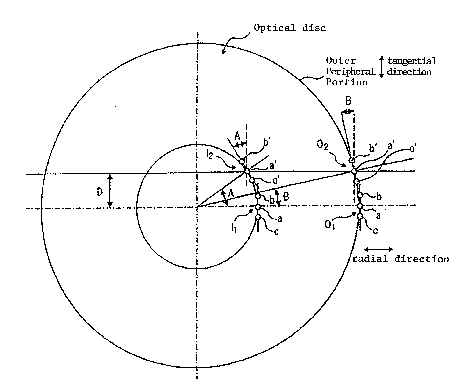
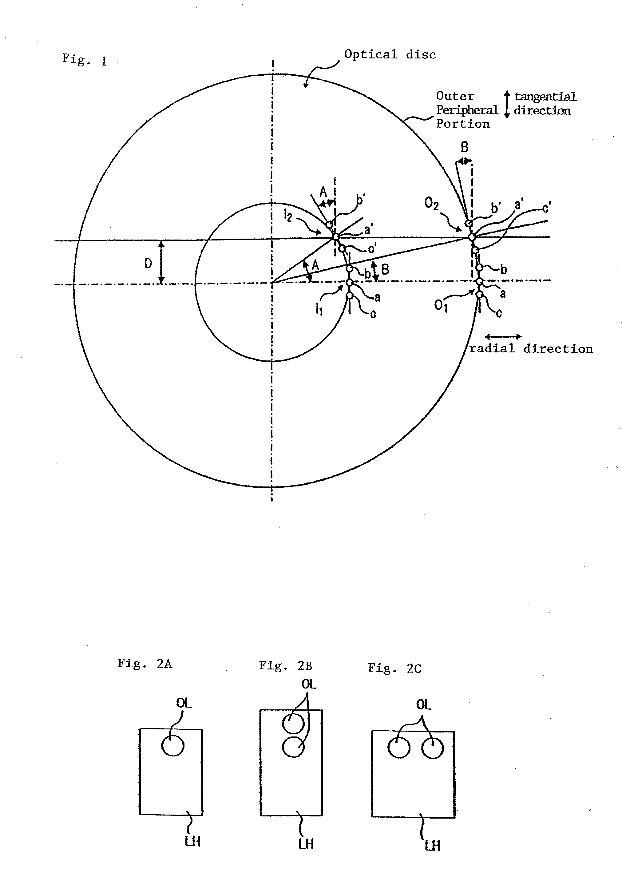
Namely, at this outer peripheral position of the optical disc, an optimal angle in the tangential direction is angle B. However, as described above, since this optical system has already been adjusted in conformity with angle A, the system is put into a state that is different from the optimal state having the optimal angle (angle B) of the three-beam method at the outer peripheral position, and is unable to obtain an optimum tacking error signal.
However, this configuration has a problem in that the width of an object lens holder LH is large so that it is not suitable for miniaturization of the optical head and the recording and replaying device, as compared with the configuration having only one object lens OL (see FIG. 2A) and with the configuration disposed with the two object lenses OL which are offset in the tangential direction (see FIG. 2B).

Method used


Image

  • Optical pickup head and optical recording and replaying device
  • Optical pickup head and optical recording and replaying device
  • Optical pickup head and optical recording and replaying device

Examples


second embodiment

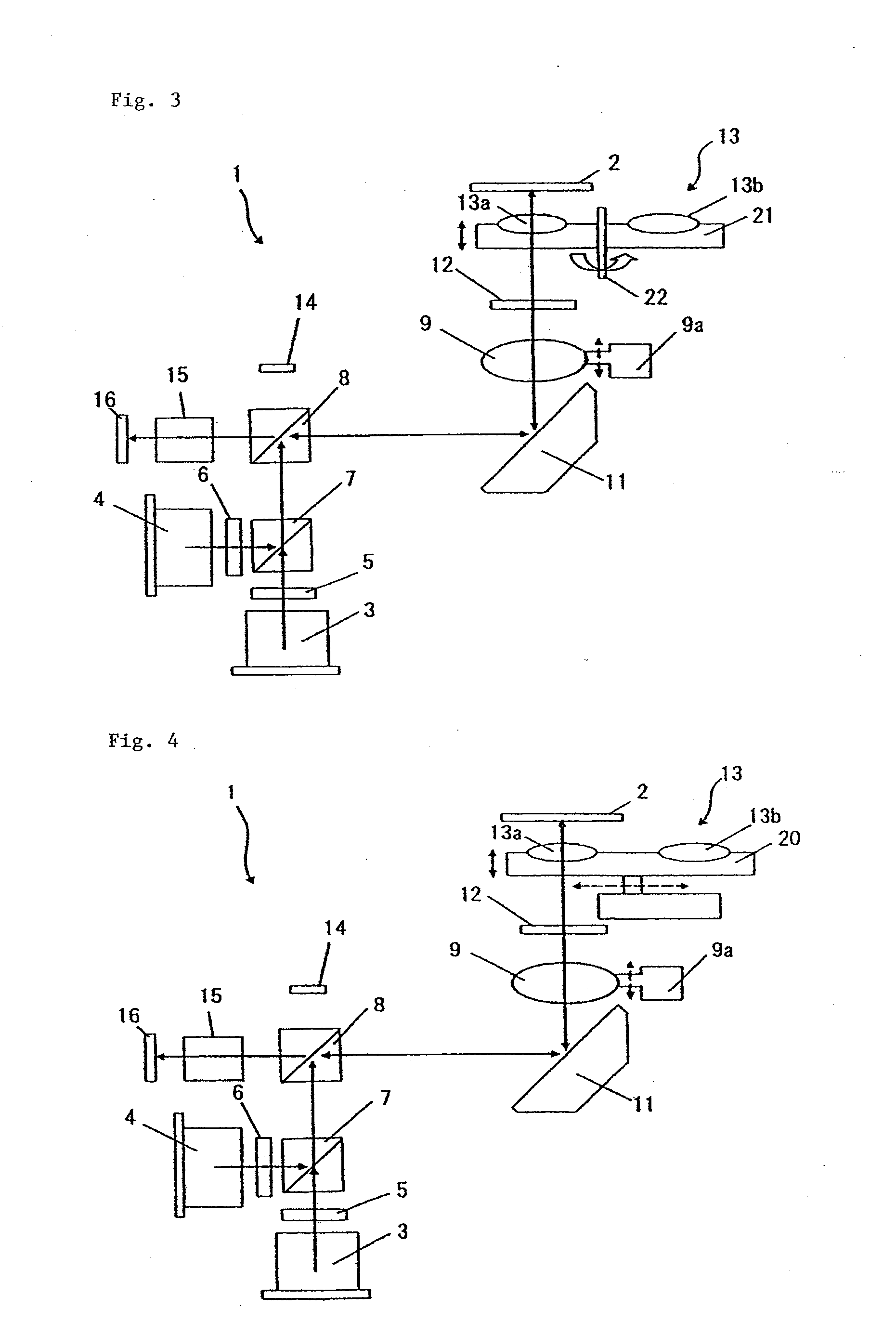
[0058]Next, the present invention will be described with reference to FIG. 4.

[0059]Similarly to the first embodiment, object lens unit 13 of the present embodiment is also configured such that object lens 13a for CD, DVD, and HD-DVD and object lens 13b for Blu-ray Disc are mounted side by side on lens holder assy (support member) 20 so that their optical axes are parallel to each other. This lens holder assy 20 can linearly and parallel move in a horizontal direction in a plane vertical to the optical axes of object lens 13a for CD, DVD, and HD-DVD and object lens 13b for Blu-ray Disc. According to the present embodiment, when CD, DVD, or HD-DVD are to be replayed as recording medium 2, object lens unit 13 is set such that object lens 13a for CD, DVD, and HD-DVD comes to a position opposite to recording medium 2. When Blu-ray Disc is to be replayed as recording medium 2, object lens unit 13 is set such that object lens 13b for Blu-ray Disc comes to a position opposite to recording m...

third embodiment

[0060]Next, the present invention will be described with reference to FIG. 5.

first embodiment

[0061]In the present embodiment, light source (semiconductor laser) 10 includes light emitting areas of the laser beams having three different wavelengths, that is, a light emitting area of a blue laser for Blu-ray Disc and HD-DVD, a light emitting area of a laser for DVD, and a light emitting area of a laser for CD which are formed at predetermined intervals from one another and which are stored inside one package. Consequently, there is no need to provide dichroic prism 7 in the outgoing path from light source 10 to object lens unit 13. However, in the return path from object lens unit 13 to light receiving elements 16a and 16b, dichroic prism 17 is disposed downstream of anamorphic lens 15. In the present embodiment, two light receiving elements 16a and 16b are provided, and light receiving element 16a receives signals from Blu-ray Disc and HD-DVD, and light receiving element 16b receives a signal from DVD and a signal from CD, respectively, so that dichroic prism 17 separates th...


PUM

PropertyMeasurementUnit
angleaaaaaaaaaa
wavelengthaaaaaaaaaa

Abstract

Optical pickup head comprises two semiconductor lasers for irradiating first to third optical beams, light receiving element for converting an optical signal into an electrical signal, and object lens unit. Object lens unit includes first object lens (object lens for CD, DVD, and HD-DVD) and second object lens (object lens for Blu-ray Disc) having a numerical aperture different from first object lens. First object lens and second object lens are moved in a tangential direction or in a radial direction of recording medium, so that first object lens and second object lens can be selectively arranged opposite to a position to be irradiated with the optical beam of recording medium.

Description

BACKGROUND OF THE INVENTION[0001]1. Field of the Invention[0002]The present invention relates to an optical pickup head and an optical recording and replaying device having the same, which are used for recording / replaying information on / from an optical recording medium.[0003]2. Description of the Related Art[0004]Recent times have seen the growth of a so-called next generation DVD, for example, a HD-DVD (High Definition DVD) and a Blu-ray Disc [registered trade mark] as an optical recording medium (optical disc) in addition to a CD (Compact Disc) and a DVD (Digital Versatile Disc). Each optical disc is different as regards the wavelength of optical beams used for optical recording and replaying and as regards the depth of layer in which recording is performed. Likewise, the numerical apertures of the object lenses of the optical pickup heads used for recording and replaying these optical discs are often different, respectively. Heretofore, to replay each of these optical discs, sepa...

Claims


Application Information

Patent Timeline
Patent Type & Authority Applications(United States)
IPC IPC(8): G11B7/135
CPCG11B7/1263G11B7/1275G11B2007/0006G11B7/1376G11B7/1374
Inventor HIROSE, KAZUNORIUNO, MASARU
Owner SAE MAGNETICS (HK) LTD
Learn More