Light fixture with an efficiency-optimized optical reflection structure

a technology of optical reflection and light fixture, which is applied in the direction of lighting and heating apparatus, instruments, coatings, etc., can solve the problems of insufficient light output for a desired illumination, insufficient light output of the light tube and the internal circuit, and conventional lighting apparatus failing to achieve the highest reflection efficiency, etc., to achieve efficiency-optimized, minimize power consumption and energy costs, and prolong the life of the lighting apparatus

Inactive Publication Date: 2009-04-09
TSAI HUNG YI
View PDF8 Cites 19 Cited by
  • Summary
  • Abstract
  • Description
  • Claims
  • Application Information

AI Technical Summary

Benefits of technology

[0008]An object of the invention is to provide efficiency-optimized illumination at a minimized power consumption and energy costs. Another object of the invention is to prolong the lifespan of a lighting apparatus by providing an optimal output of reflective light, thereby reducing the level of greenhouse effect on the light space. Still another object of the invention is to provide a uniform output of reflective light by rapid focus adjustment.

Problems solved by technology

Also, the temperature rise will inevitably ruin the structure of the luminaire so that the light tube and the internal circuits deteriorate acceleratively.
Second, due to the reflex louver 13 as well, most of the light emitted from the light tube 12 cannot be reflected out of the lamp housing efficiently, leading to an insufficient light output for a desired illumination.
In other words, the conventional lighting apparatus fails to achieve highest reflection efficiency.
Accordingly, a relatively large percentage of light energy goes to waste when using the conventional lighting apparatus, which is diametrically opposed to the worldwide trend towards energy-saving and carbon-reduction policies.

Method used


Image

  • Light fixture with an efficiency-optimized optical reflection structure
  • Light fixture with an efficiency-optimized optical reflection structure
  • Light fixture with an efficiency-optimized optical reflection structure

Examples


Embodiment Construction

[0019]The invention will be described with reference to illustrative examples in the following. However, it should be understood by one of ordinary skill in the art that the invention may be practiced without some or all of these specific details. In other instance, well known process operations have not been depicted in detail in order not to unnecessarily obscure the invention.

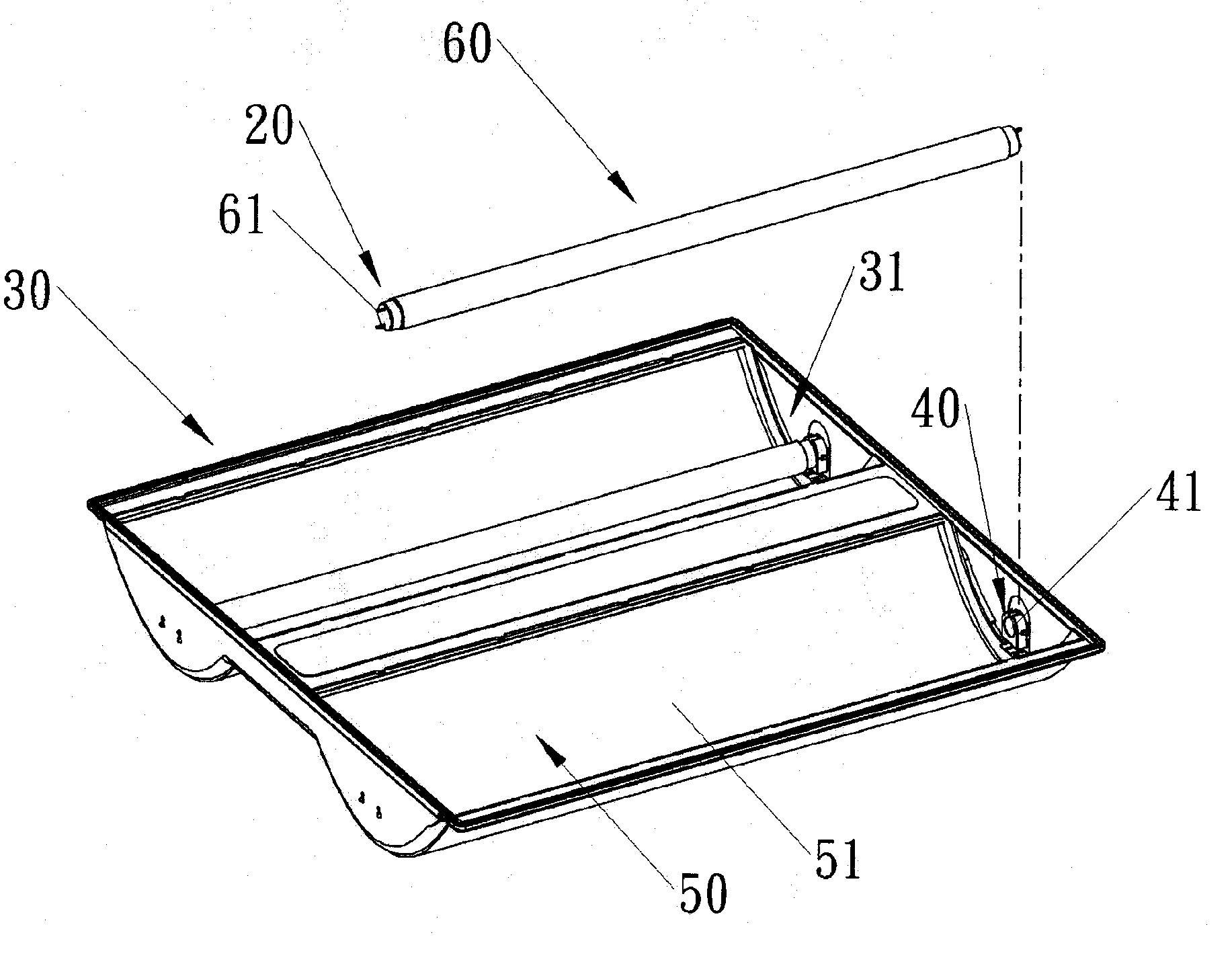
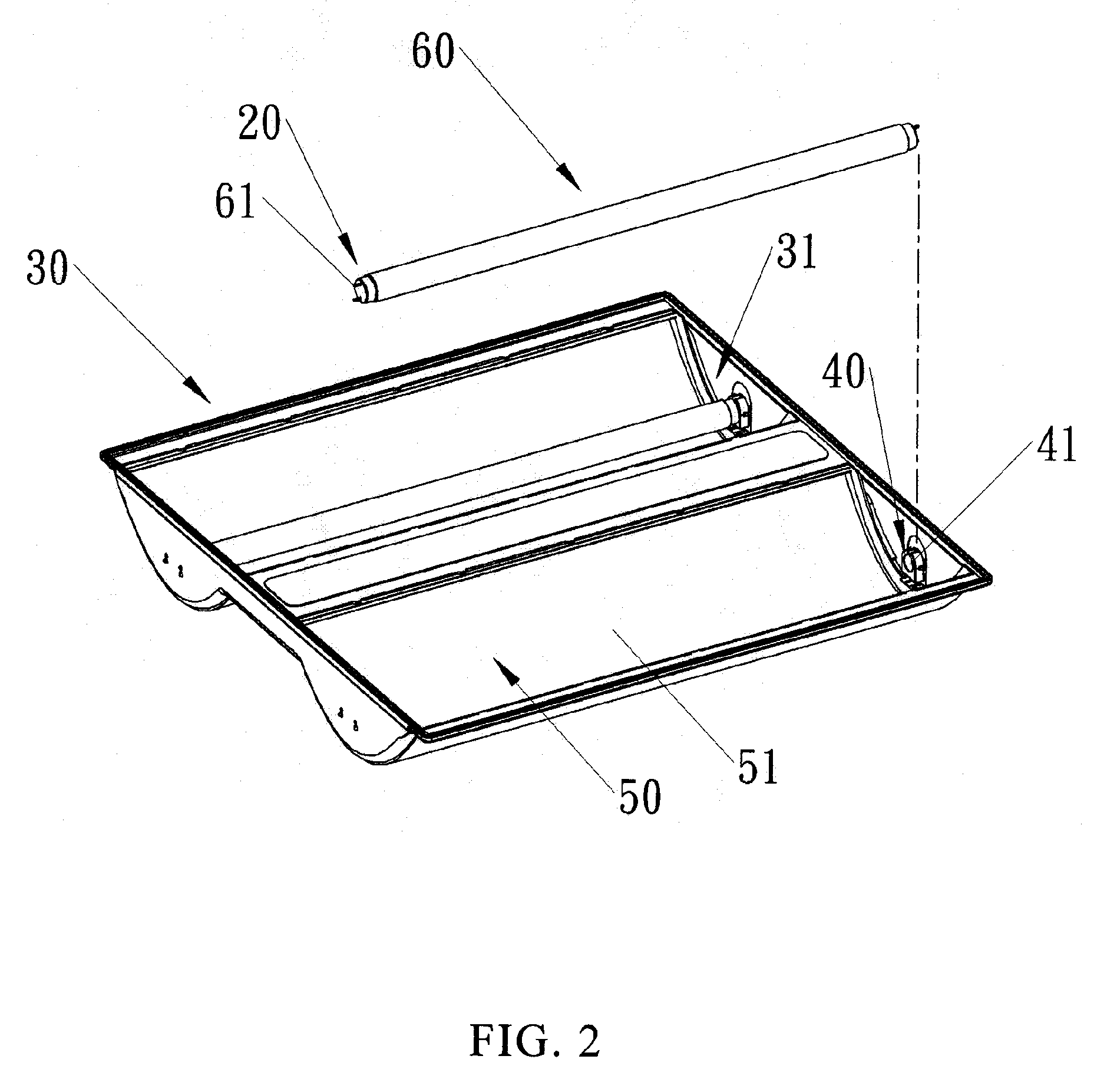
[0020]For example, FIG. 2 shows the lighting apparatus 20 of one aspect of the invention, which includes a lamp housing 30, four connectors 40, and two reflectors 50 each having a curved surface 51, wherein two light tubes 60 can be received in two open accommodating spaces 31 respectively by the connectors 40. The word “open” means that the accommodating space 31 provides a region for the light emitted from the light tube to “interact” with the surroundings and this should not be interpreted as a limiting condition. The lamp housing 30 may be made from, for example, aluminum or iron, or any other suitable m...


PUM

PropertyMeasurementUnit
thicknessaaaaaaaaaa
thicknessaaaaaaaaaa
thicknessaaaaaaaaaa

Abstract

A light fixture with an optical reflection structure, comprising a lamp housing having at least one open accommodating space for light beam to be emitted outward therefrom; a plurality of connectors for coupling a light tube to the light fixture, the connectors being located at both opposite ends in a longitudinal direction of the accommodating space; a reflector having a curved surface affixed with a composite mirror film for light reflection, the reflector being located in the accommodating space and substantially covering at least a part of a surface of the accommodating space, wherein the curved surface is determined based on law of reflection by optimizing a luminous flux of primary reflection light reflected off the reflector to the extent of 90% or more compared with a naked light source from the light tube. The light fixture of the invention provides sufficient illumination and prolongs the lifespan of the light tube in a cost-economic way, thus directly saving energy and reducing the production of carbon.

Description

BACKGROUND OF THE INVENTION[0001]a) Field of the Invention[0002]The invention relates generally to a lighting structure, and more particularly, to a light fixture with an optical reflection structure for efficient illumination.[0003]b) Description of the Related Art[0004]The invention of lamps contributes a lot to the modern society. Realistically speaking, lighting apparatus (luminaire) has become essential to our daily lives today. In general, the conventional lighting apparatus 10 as shown in FIG. 1 includes a lamp housing 11 having an accommodating space 111, at least one light tube 12, and a reflex louver 13, in which the light tube 12 and the reflex louver 13 are disposed within the accommodating space 111 of the lamp housing 11, with the light tube 12 located between the lamp housing 11 and the reflex louver 13. However, according to optical reflection principle, conventional design of the lighting apparatus needs to be improved significantly in terms of the following points....

Claims


Application Information

Patent Timeline
Patent Type & Authority Applications(United States)
IPC IPC(8): F21V7/08F21V7/04
CPCG02B1/111F21V7/22F21V7/28
Inventor TSAI, HUNG-YI
Owner TSAI HUNG YI
Why Eureka
Try Eureka