
Method for improved forensic analysis

a forensic analysis and multi-view technology, applied in image enhancement, instruments, computing, etc., can solve the problems of difficult interpretation or confidence of graphs by other non-experts, extreme sensitive methods, and limited use materials, and achieve the effect of providing additional clarity over the single snapshot imag

Inactive Publication Date: 2009-04-09
CHEMIMAGE
View PDF4 Cites 8 Cited by
  • Summary
  • Abstract
  • Description
  • Claims
  • Application Information

AI Technical Summary

Benefits of technology

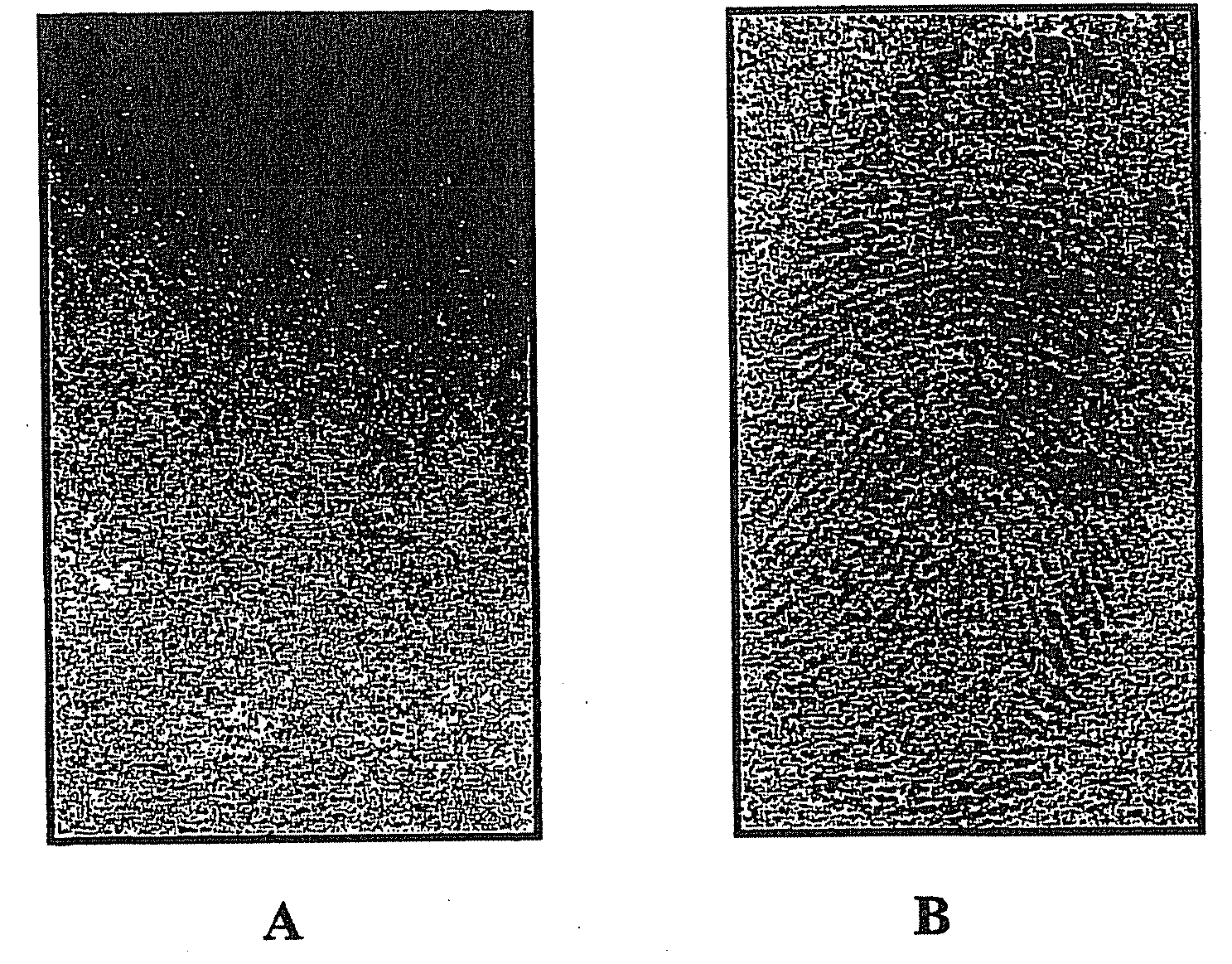
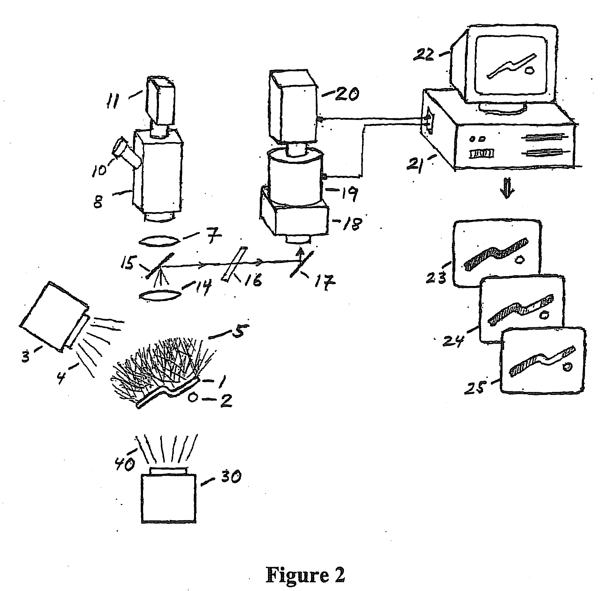
[0014]In the multi-view approach of the present invention, the reflection, emission or scattering of this incident illumination at a plurality of wavelengths over the entire image of the forensic specimen is examined to create multiple views of the specimen. No tuning of the incident radiation is required to perform this analysis. The multiple views are captured digitally and computer processed to show how the forensic material signals vary at any point (pixel) in the sample over the entire filed of view. These chemical spatial variations can then be processed with a computer to be identified and mapped onto the original image, thereby providing additional clarity over the single snapshot image.

Problems solved by technology

Many of these methods are extremely sensitive and require finite material for their use that is consumed as part of the analysis process.
However, the principles of such methods and the resulting graphs can be difficult for other non-experts to interpret or place confidence in.
Thus, when presenting this evidence in courtrooms, such techniques may not be sufficiently understood to provide convincing or compelling evidence.
Despite the existence of many advanced scientific techniques and analysis methods that are very sophisticated, many such techniques may not be understood by non-specialists, and may thereby raise some doubts as to its validity.
One difficulty with systems of the prior art is their relative lack of dynamic range and resolution, making it difficult to clearly differentiate small, subtle or minute variations over the forensic sample.
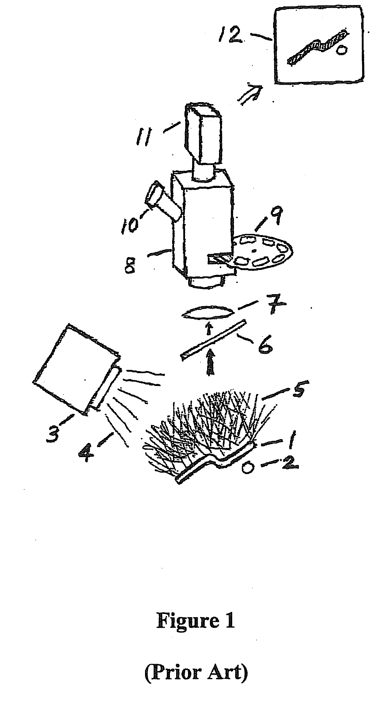
Prior art systems produce a single image at a given wavelength or set of wavelengths of emitted radiation, making it impossible to view or obtain data from minute portions or different regions of the overall sample if the emitted radiation varies slightly within the sample or compared to the background substrate or sample matrix.

Method used


Image

  • Method for improved forensic analysis
  • Method for improved forensic analysis
  • Method for improved forensic analysis

Examples


Embodiment Construction

[0046]FIG. 2 shows a schematic of the multi-view forensic scope of the present invention. The scope of the present invention consists of multi-view optical train 18, electronic view selector 19 and image sensor 20. Multi-view optical train 18 accepts the sample light and matches its spatial characteristics to electronic view selector 19, the output of which is captured by image sensor, 20. Mirrors 15 and 17 direct radiation which is emitted, scattered or reflected from specimen 1 into the multi-view scope. An optional intermediate filter 16 can be used to filter out certain undesirable components from the scattered, emitted or radiated radiation to optimize the performance of the multi-view optical train 18. Computer 21 controls electronic view sensor 19 and collects data from image sensor 20 for storage and processing. Images of the processed data are rendered on display 22. The multi-view scope configuration shown in FIG. 2 allows for sample viewing with a conventional forensic sc...


PUM


Abstract

A method for improved forensic analysis using multi-view digital imaging of forensic specimens at a plurality of reflected, scattered, emitted, transmitted or absorbed wavelengths to provide new detailed information to distinguish and differentiate forensic materials and samples.

Description

REFERENCE TO RELATED APPLICATIONS[0001]This application claims priority pursuant to 35 U.S.C. § 119(e) to U.S. Provisional Application No. 60 / 422,604, filed Oct. 31, 2002.FIELD OF THE INVENTION[0002]The present invention relates to the field of forensic analysis and, more specifically, to the use of multi-view digital imaging of forensic samples at multiple reflected, scattered, emitted, transmitted or absorbed wavelengths to provide new, detailed information to distinguish and differentiate forensic materials and samples. This method allows more subtle forensic features to be observed and related to the image of the sample or to known reference samples than heretofore possible.BACKGROUND OF THE INVENTION[0003]Forensic analysis involves the observation and identification of an object that may exist in part or in its entirety on some sort of supporting surface. This analysis typically compares the sample in question to other possible reference samples or reference data to make an ass...

Claims


Application Information

Patent Timeline
Patent Type & Authority Applications(United States)
IPC IPC(8): G06K9/00G06T5/50G06V10/143G06V40/13
CPCG06K9/00013G06T5/50G06K2009/00946G06K9/2018G06V40/13G06V40/155G06V10/143
Inventor TREADO, PATRICK J.EXLINE, DAVID L.WOLFE, JULIANNE
Owner CHEMIMAGE
Learn More