
Transmission rate control method, mobile station and radio base station

a technology of transmission rate and control method, which is applied in the direction of data switching network, frequency-division multiplex, instruments, etc., can solve the problems of high cost of implementing an apparatus and operating a network, difficult to perform fast control of the transmission rate change of the channel, and high traffic compared with voice communications or tv communications, so as to prevent a decrease in the transmission rate and improve the radio quality

Active Publication Date: 2009-04-09
NTT DOCOMO INC
View PDF8 Cites 8 Cited by
  • Summary
  • Abstract
  • Description
  • Claims
  • Application Information

AI Technical Summary

Benefits of technology

[0018]The present invention has been made in view of the above-described problems, and its object is to provide a transmission rate control method, a mobile station, and a radio base station that make it possible to improve a radio quality by preventing a decrease in a transmission rate of uplink user data, the decrease unintended by the radio base station Node B and caused by a false detection of a “Down” command in an RGCH, in the conventional mobile communication system using an “Enhanced Uplink.”

Problems solved by technology

In general, data communications often cause burst traffic compared with voice communications or TV communications.
Therefore, in the conventional mobile communication system, there has been a problem that it is difficult to perform fast control for changing of the transmission rate of channel (for example, per approximately 1 through 100 ms), due to processing load, processing delay, or the like.
In addition, in the conventional mobile communication system, there has also been a problem that costs for implementing an apparatus and for operating a network are substantially increased even ff the fast control for changing of the transmission rate of the channel can be performed.
However, there has been a problem that, if the mobile station UE assumes a “DTX” included in the RGCH as the “Down” command, the mobile station UE decreases the transmission rate of the uplink user data, thereby a decrease unintended by the radio base station Node B in the transmission rate occurs.

Method used


Image

  • Transmission rate control method, mobile station and radio base station
  • Transmission rate control method, mobile station and radio base station
  • Transmission rate control method, mobile station and radio base station

Examples


Embodiment Construction

(Mobile Communication System According to a First Embodiment of the Present Invention)

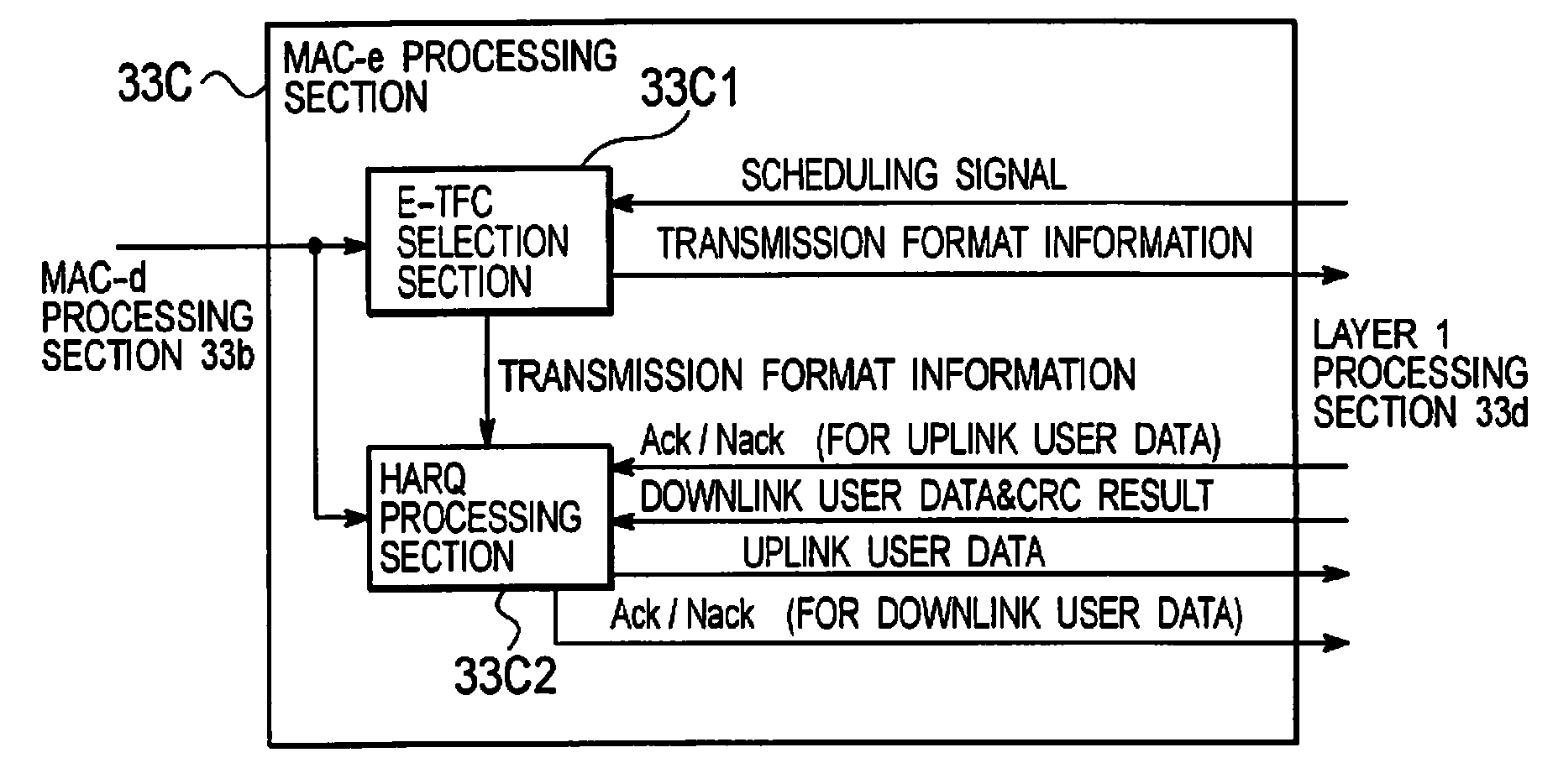
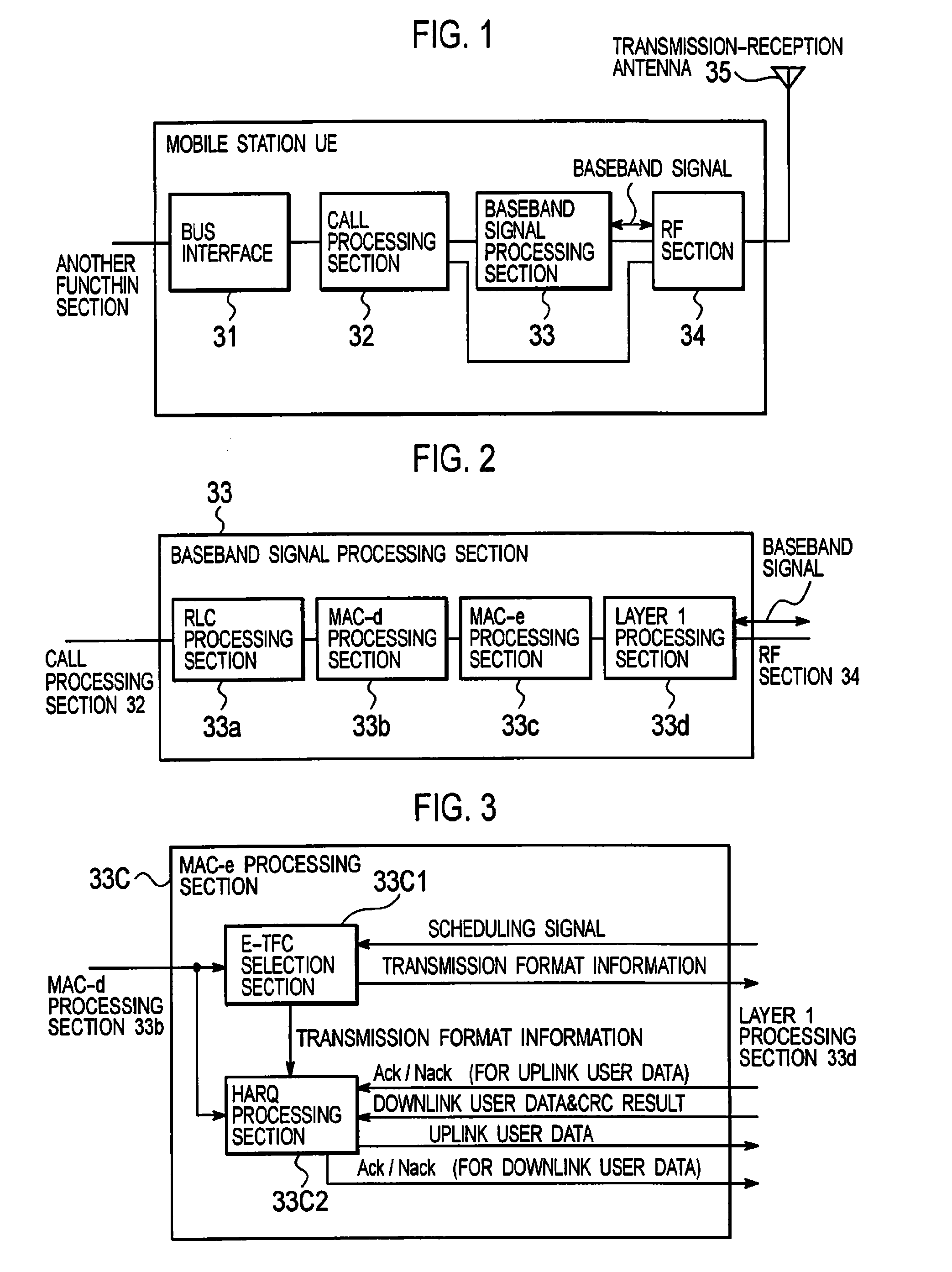
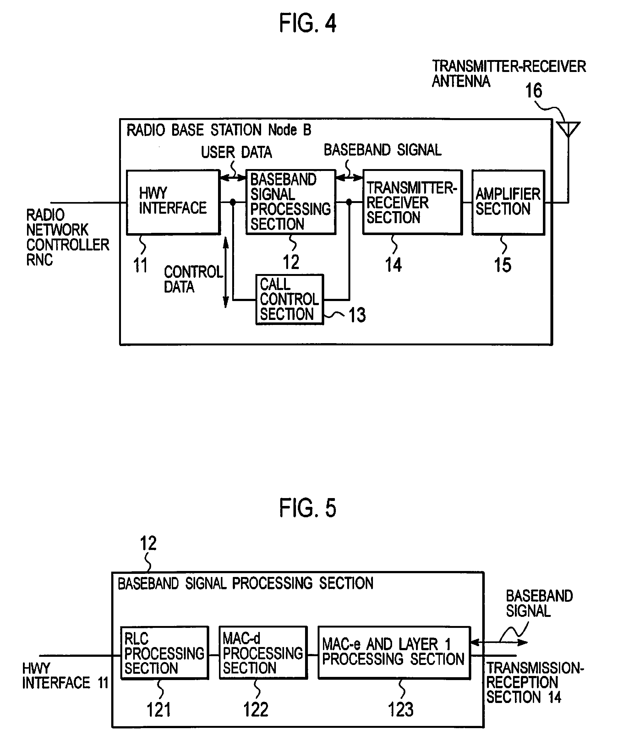
[0035]An explanation will be given for the configuration of a mobile communication system according to a first embodiment of the present invention with reference to FIGS. 1 to 8. Note that the mobile communication system according to this embodiment includes a plurality of radio base stations Node B#1 to #5 and a radio network controller RNC, as shown in FIG. 11.

[0036]In addition, in the mobile communication system according to this embodiment, a “High Speed Downlink Packet Access (HSDPA)” is used in a downlink, and an “Enhanced Uplink (EUL)” is used in an uplink. It should be noted that in both of the HSDPA and the EUL, retransmission control (N process stop and wait) shall be performed by a “Hybrid Automatic Repeat Request (HARQ)”.

[0037]Therefore, an Enhanced Dedicated Physical Channel (E-DPCH), configured of an Enhanced Dedicated Physical Data Channel (E-DPDCH) and an Enhanced Dedicated Physical...


PUM


Abstract

In the conventional mobile communication system using an “Enhanced Uplink, the present invention improves a radio quality by preventing a decrease in a transmission rate of uplink user data, the decrease unintended by the radio base station Node B and caused by a false detection of a “Down” command in an RGCH.” A transmission rate control method according to the present invention includes: transmitting, from a radio base station to a mobile station, a relative transmission rate control channel for instructing to decrease the transmission rate of the uplink user data, only when the uplink user data transmitted from the mobile station has been successfully received.

Description

TECHNICAL FIELD [0001]The present invention relates to a transmission rate control method, a mobile station, and a radio base station, which controls a transmission rate of uplink user data.BACKGROUND ART [0002]In a conventional mobile communication system, in an uplink from a mobile station UE to a radio base station Node B, a radio network controller RNC is configured to determine a transmission rate of a dedicated channel, in consideration of radio resources of the radio base station Node B, an interference volume in an uplink, transmission power of the mobile station UE, transmission processing performance of the mobile station UE, a transmission rate required for an upper application, and the like, and to notify the determined transmission rate of the dedicated channel by a message in a layer-3 (Radio Resource Control Layer) to both of the mobile station UE and the radio base station Node B.[0003]Here, the radio network controller RNC is provided at an upper level of the radio ...

Claims


Application Information

Patent Timeline
Patent Type & Authority Applications(United States)
IPC IPC(8): H04B7/005H04W28/22
CPCH04W28/22H04B7/264
Inventor UMESH, ANILUSUDA, MASAFUMI
Owner NTT DOCOMO INC
Learn More