Catheter device

a catheter and shaft technology, applied in carpet cleaners, cleaning machines, therapy, etc., can solve the problems of limiting the speed of sealing, and achieve the effect of painting the rotatability of the drive sha

Active Publication Date: 2009-04-09
AIS AACHEN INNOVATIVE SOLUTIONS
View PDF10 Cites 300 Cited by
  • Summary
  • Abstract
  • Description
  • Claims
  • Application Information

AI Technical Summary

Benefits of technology

[0019]Via a rinsing bore in the clutch housing it is possible to introduce a rinsing medium to lubricate the drive shaft and the output-side clutch element. This prevents blood from penetrating into the area between the drive shaft and the catheter body, and impairing the rotatability of the drive shaft.
[0020]Preferably an output-side clutch element carrying the distal magnet unit is supported by a sliding bearing. By this means the distance between the two magnet units may be set precisely.
[0021]In accordance with a development, an additional magnet ring bearing is provided. On the one hand this provides further and especially radial support for the output-side clutch element, and on the other hand it is able to counteract the forces exerted by the magnet units, so that the force with which the output-side clutch element is pressed against the sliding bearing is reduced.

Problems solved by technology

Any such feed-through would require sealing, but such sealing limits the speed.

Method used


Image

  • Catheter device
  • Catheter device
  • Catheter device

Examples


Embodiment Construction

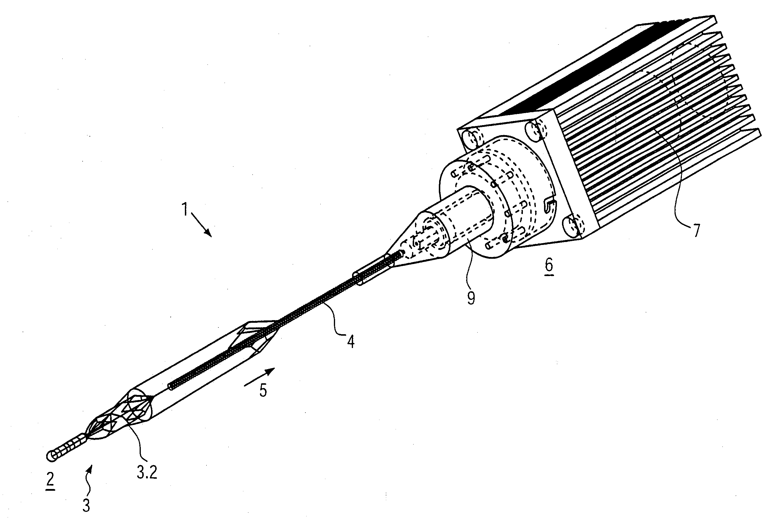
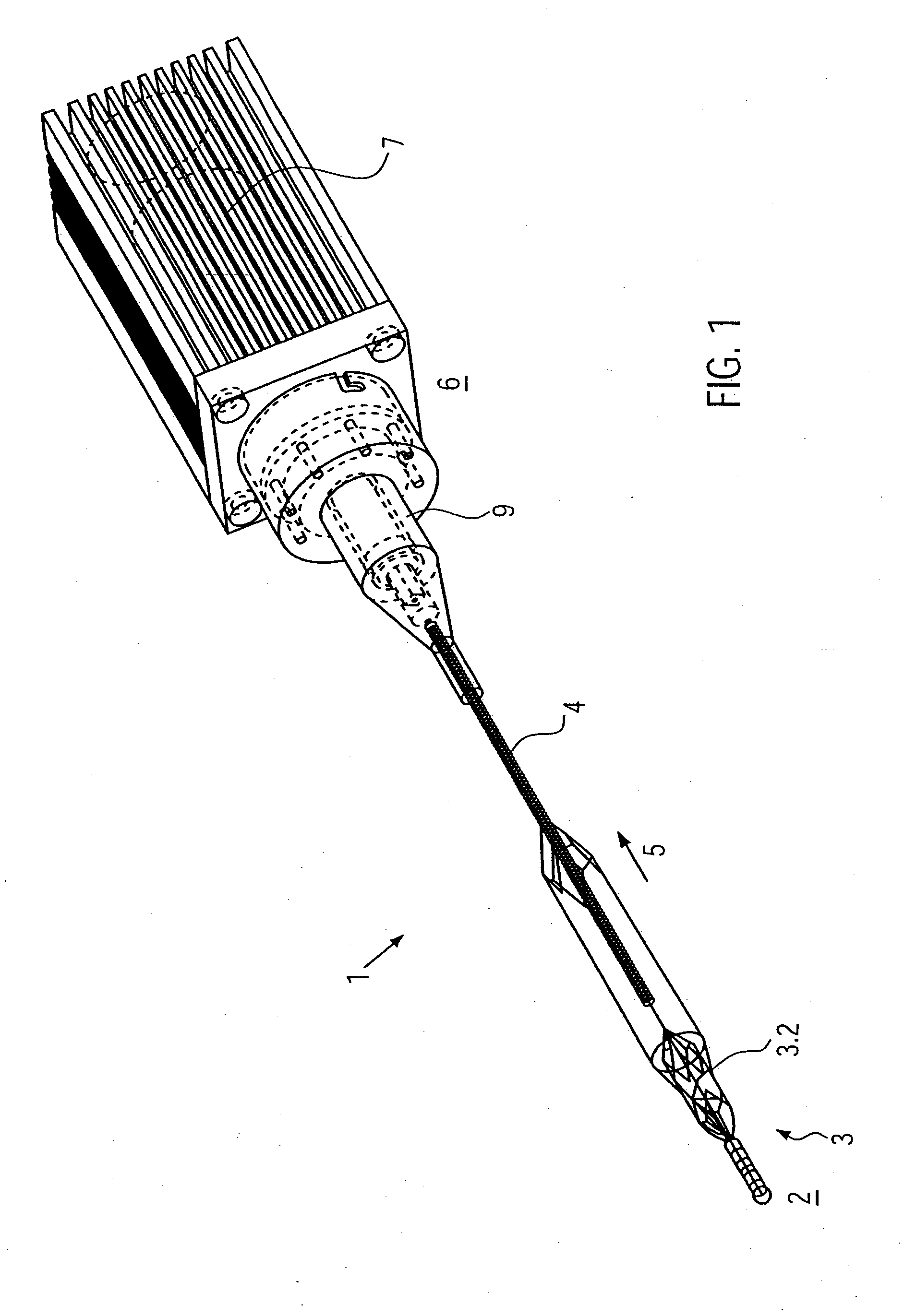
[0028]FIG. 1. shows a perspective view of a catheter device according to the invention.

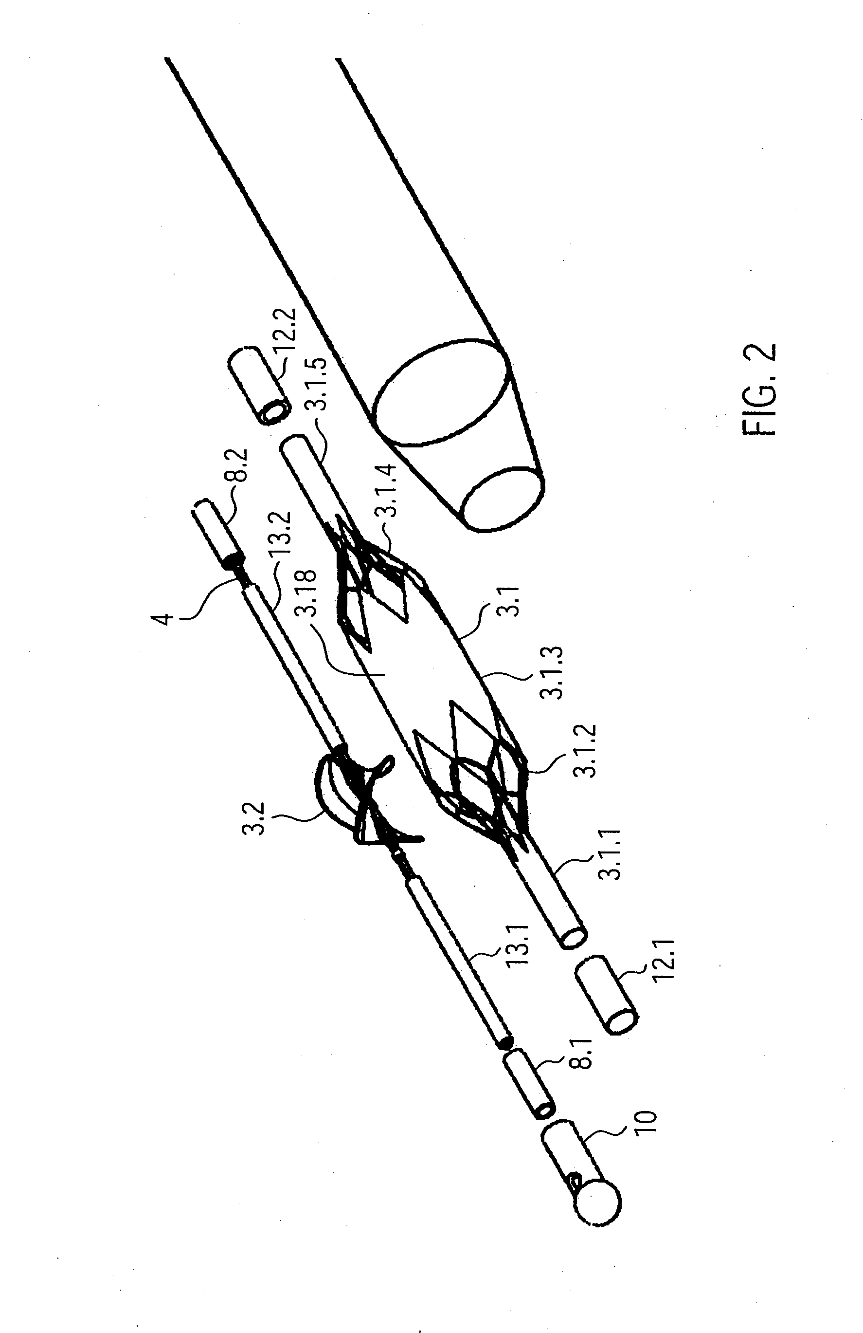
[0029]FIG. 2. shows an exploded drawing of a catheter device according to the invention.

[0030]FIG. 3. shows a body cap of the catheter device shown cut away at the side.

[0031]FIG. 4. shows a distal catheter body element of the catheter device in a cut-away side view.

[0032]FIG. 5. shows a connection bush of the catheter device in a cut-away side view.

[0033]FIG. 6. shows a pump of the catheter device with support in a cut-away side view.

[0034]FIG. 7A shows a section along the line A-A through the distal connection bush of the catheter device as shown in FIG. 6.

[0035]FIG. 7B shows a section along the line B-B through the proximal connection bush of the catheter device of FIG. 6.

[0036]FIG. 8. shows a mesh structure of a pump housing of the catheter device.

[0037]FIG. 9. shows a detail of the mesh structure of the pump housing of the catheter device.

[0038]FIG. 10. shows a drive shaft with guide spiral a...


PUM


Abstract

The catheter device comprises a motor located at the proximal end of the catheter device and a drive shaft, extending from the proximal end section to the distal end section of the catheter device, for driving a rotating element located at the distal end of the catheter device. The catheter device also comprises a hose-like catheter body which encompasses the drive shaft and extends from the proximal end section to the distal end section of the catheter device. At the proximal end of the catheter device, the drive shaft is connected to a motor by a clutch. The clutch is a magnetic clutch with a proximal and a distal magnet unit. The proximal magnet unit is connected to the motor and the distal magnet unit to the drive shaft. The distal magnet unit is mounted fluid-tight in a clutch housing. The proximal end of the catheter body makes a fluid-tight connection with the clutch housing.

Description

CROSS-REFERENCE TO RELATED APPLICATION[0001]This application claims priority to U.S. Provisional Application No. 60 / 978,256 filed in the United States Patent and Trademark Office on Oct. 8, 2007, the contents of which are hereby incorporated by reference herein for all purposes.BACKGROUND OF THE INVENTION[0002]1. Technical Field[0003]The invention relates to a catheter device, in particular a catheter device with an elongated drive shaft.[0004]2. Related Art[0005]Implantable blood pumps are used increasingly in the treatment of patients with serous heart conditions. Such blood pumps have so far been provided mainly for long-term use. However, blood pumps are also being developed which are designed for short-term support for the heart and may be inserted by minimally invasive means. Here the medical objectives are stress-relief for and recovery of the heart, or to provide bridging until a possible heart transplant. The range of application of such pumps depends on the one hand on the...

Claims


Application Information

Patent Timeline
Patent Type & Authority Applications(United States)
IPC IPC(8): A61M1/00A61M60/13A61M60/237A61M60/414A61M60/808A61M60/82A61M60/865A61M60/896
CPCA61B17/320758A61B2017/320775A61M1/101A61M1/125A61M1/1024A61M1/1034A61M1/1015A61M60/82A61M60/829A61M60/414A61M60/148A61M60/808A61M60/865A61M60/896A61M60/237A61M60/13A61M60/419A61M60/422
Inventor PFEFFER, JOACHIM GEORGSCHMITZ-RODE, THOMASGUNTHER, ROLF W.
Owner AIS AACHEN INNOVATIVE SOLUTIONS
Why Eureka
Try Eureka