Adjustment device for a camshaft

Inactive Publication Date: 2009-04-16
ZF FRIEDRICHSHAFEN AG
View PDF4 Cites 2 Cited by
  • Summary
  • Abstract
  • Description
  • Claims
  • Application Information

AI Technical Summary

Benefits of technology

[0010]By virtue of the design concept costs are reduced, since no expensive, non-contact systems are needed and the fail-safe locking means necessary in the system can be co-actuated conjointly with the shift movement of the friction lining. In this way, an entire actuator can advantageously be saved.

Problems solved by technology

Owing to the necessary components that work without contact, such systems are disadvantageously expensive and they also require fail-safe, locking means for which an additional actuator is needed.

Method used


Image

  • Adjustment device for a camshaft
  • Adjustment device for a camshaft

Examples


Embodiment Construction

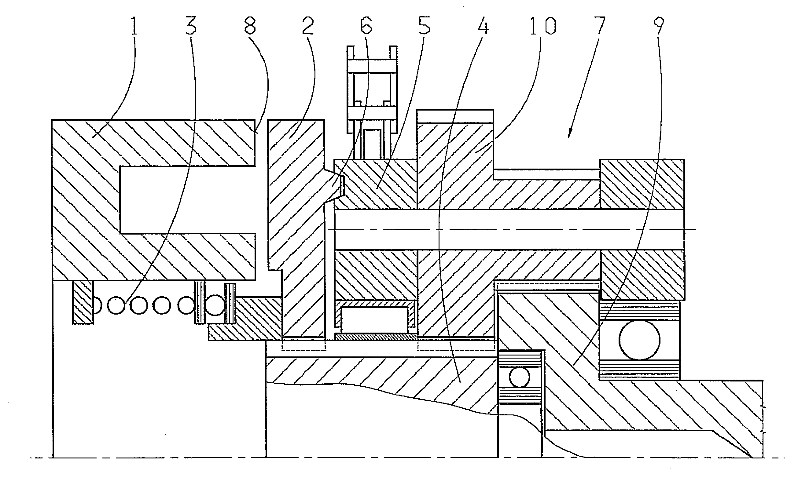
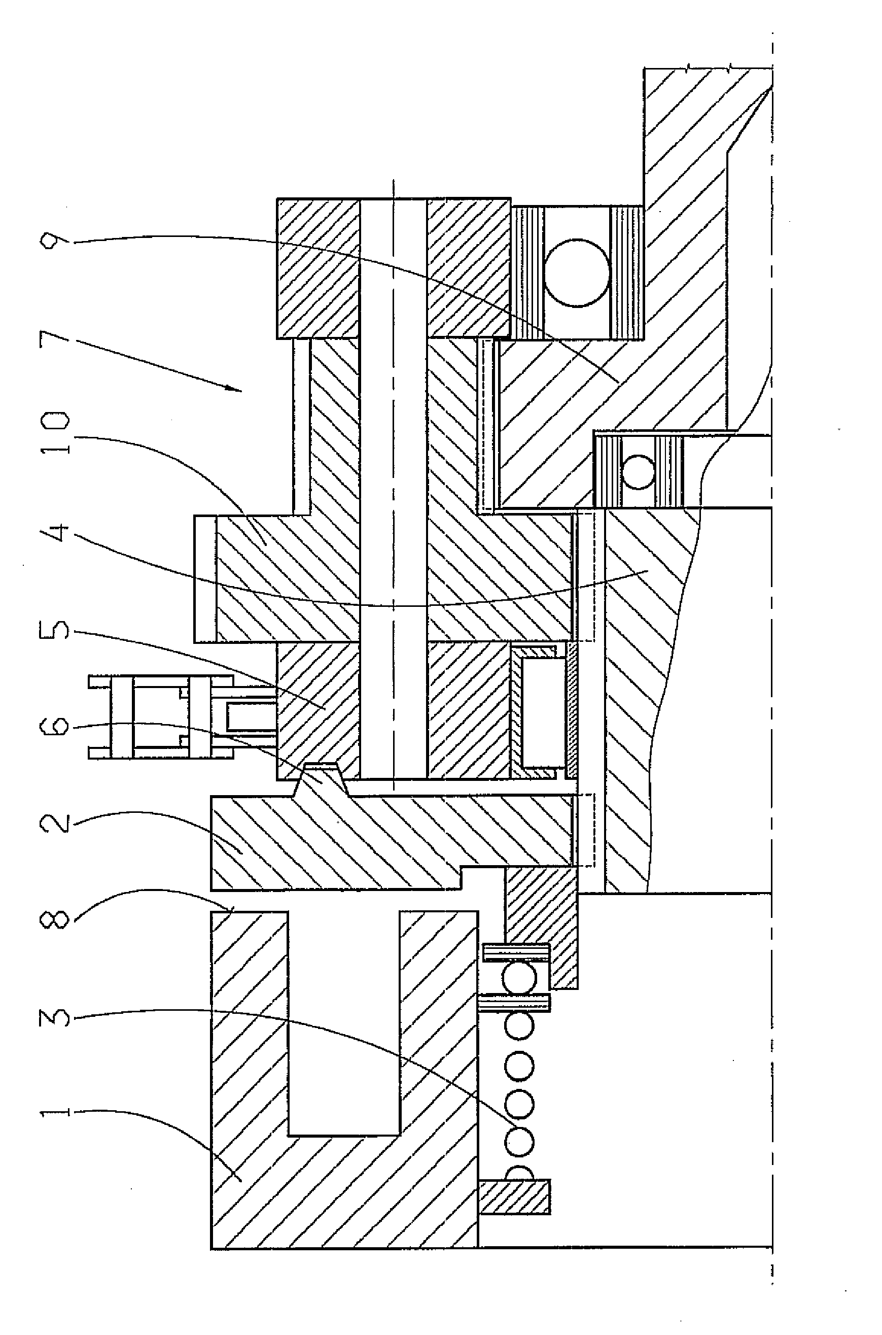
[0013]A frictional brake system with additional mechanical locking of an adjustment device, according to the invention, comprises an electrically actuated shift solenoid 1, which has a friction surface 8, a magnetic friction lining 2 with a locking element 6 and a spring 3, such that the locking element 6 co-operates with an element 5 of a superposition gear system 7 on the drive input side. The friction lining 2 is attached axially, movably, but rotationally fixed on a spur gear 4 of the superposition gear system 7.

[0014]In the embodiment illustrated, the superposition gear system 7 is made as a transmission with two solar spur gears 4, 9 and a two-stage planetary gear 10. The camshaft is connected rotationally fixed to the second spur gear 9 of the superposition gear system 7. The drive input is connected to the planetary gear carrier.

[0015]When the superposition gear system 7 is made as a planetary transmission it is advantageous to arrange the friction lining 2 on the teeth of t...


PUM


Abstract

An adjustment device for a camshaft includes a brake system and a superposition gear system connected on a drive output side to the camshaft and on the drive input side to the crankshaft, such that to adjust the camshaft the superposition gear system dissipates part of the energy from the drive side into the brake system. The brake system is a frictional brake system, such that the necessary braking force is produced by a friction lining that operates in a slipping condition.

Description

[0001]This application is a national stage completion of PCT / EP2007 / 051306 filed Feb. 12, 2007, which claims priority from German Application Serial No. 10 2006 011 806.5 filed Mar. 15, 2006.FIELD OF THE INVENTION[0002]The present invention concerns an adjustment device for a camshaft.BACKGROUND OF THE INVENTION[0003]From the prior art, it is known to produce the adjustment movement of the camshaft by way of wear-free and no-contact brake systems.[0004]An adjustment device for a camshaft of an internal combustion engine is known from DE 103 55 560 A1, which comprises a drive input element driven by a crankshaft of the engine, a drive output element that drives the camshaft of the engine and a control element, which is acted upon by a brake, such that a relative rotation between the drive input element and the drive output element can be produced by varying the braking torque on the control element. In this, the structural form of the adjustment device allows any desired phase angle ...

Claims


Application Information

Patent Timeline
IPC IPC(8): F01L1/352
CPCF01L1/352Y10T74/2102F01L2820/01F01L2810/02F01L1/344F01L1/047
Inventor RICHTER, FRANK
Owner ZF FRIEDRICHSHAFEN AG
Why Eureka
Try Eureka