Container for transporting cooled goods

Active Publication Date: 2009-04-16
ROCHE DIAGNOSTICS OPERATIONS
16 Cites 8 Cited by

AI-Extracted Technical Summary

Problems solved by technology

However, these containers frequently have the drawback, that with a temperature below the freezing point inside of the container, the exterior walls of the container also have a temperature below 0° C. Therefore, when this co...

Benefits of technology

[0010]The present invention avoids the disadvantages of the prior art by providing a container for transporting cooled g...

Abstract

The invention refers to a container for transporting cooled goods, comprising an inner container for receiving the cooled goods and an outer container surrounding the inner containers. The inner container contains a thermally insulating material and has an outer surface on which outer ribs are arranged. The outer ribs generate spaces between the inner container and the outer containers. The outer container has a plurality of ventilation holes for ventilating the spaces.

Application Domain

Domestic cooling apparatusLighting and heating apparatus +12

Technology Topic

EngineeringMechanical engineering

Image

  • Container for transporting cooled goods
  • Container for transporting cooled goods
  • Container for transporting cooled goods

Examples

  • Experimental program(1)

Example

[0032]In FIG. 1 an outer container is shown in a perspective view from the outside.
[0033]Two side walls 2, 3 and the top 4 of the outer container 1 are visible in FIG. 1. In one embodiment the shown outer container 1 is a cardboard box. The outer container 1 has a plurality of ventilation holes 5 for allowing an air exchange between its inside and its outside. The ventilation holes 5 are distributed over all of the walls of the outer container, including its four side walls (2, 3), its base and its top 4. The top 4 contains six ventilation holes 5. It is constructed by two flaps 6, which are covering the outer container 1, each flap 6 containing three ventilation holes 5 aligned in the middle of each flap 6. The ventilation holes 5 of the top 4 are all of a rectangular form. The first side wall 2 (shown on the right side) contains twelve ventilation holes 5, which enframe the middle region 7 of the first side wall 2 with a small distance d from its edges 8. Four ventilation holes 5 in the four corners of the first side wall 2 are of a triangular form. Between every two triangular ventilation holes 9 of neighboring corners, two rectangular ventilation holes 10 are positioned.
[0034]The second side wall 3 (shown in the front) contains fourteen ventilation holes 5, twelve of which are arranged in a similar way as the ventilation holes 5 of the first side wall 2. Two additional rectangular ventilation holes 11 are placed in the middle region 12 of the second side wall 3.
[0035]The outer container 1 as shown in FIG. 1 is designed to accommodate an inner container as shown in FIG. 2.
[0036]In FIG. 2 an inner container is shown in a perspective view from the outside.
[0037]Two side walls 13, 14 and the top 15 of the inner container 16 are visible inFIG. 2. In one embodiment the shown inner container 16 is made of a thermally insulating foamed plastics material, and in another embodiment of expanded polystyrene. The inner container 16 has an outer surface 17 on which outer ribs are arranged. When the inner container 16 as shown in FIG. 2 is placed within an outer container 1 as shown in FIG. 1, the outer ribs 18 have the function of spacers, generating spaces between the inner container 16 and the outer container 1, which are ventilated via the ventilation holes 5 of the outer container 1.
[0038]The inner container 16 according to FIG. 2 is closed by a lid 19, which covers its top 15. All of the outer ribs 18 have a rectangular cross section. The four outer ribs 20, which are arranged on each side wall 13, 14 of the inner container 16, run in the form of bars 21 from bottom to top of the respective side wall 13, 14. These bars 21 are resumed by sixteen square ribs 22 at the edge of the top 15 and the base 23 (not shown). Furthermore, the top 15 has another sixteen square ribs 24, which are evenly distributed over its surface 17. The base 23 is in one embodiment designed similarly. The rib height of all of the outer ribs of the inner container 16 according to FIG. 2 is in one embodiment 10 mm.
[0039]When an inner container 16 according to FIG. 2 is placed within an outer container 1 according to FIG. 1 to form a container for transporting cooled goods according to the invention, the outer ribs 18 of the inner container 16 abut the inner surfaces of the outer container 1 at positions, where no ventilation holes 5 are arranged. The positions of the ribs 18 are shifted with respect to the ventilation holes 5. In the regions 25 of the outer surface 17 of the inner container 16 without outer ribs 18 spaces are formed between the inner container 16 and the outer container 1, which are ventilated via the ventilation holes 5 of the outer container 1.
[0040]In FIG. 3 an outer container is shown in a perspective view from the outside.
[0041]Two side walls 2, 3 and the top 4 of the outer container 1 are visible in FIG. 3. In one embodiment the shown outer container 1 is a cardboard box. The outer dimensions of the outer container are e.g. 770×595×710 mm3 (quality 2.60 BC). The outer container 1 has a plurality of ventilation holes 5 for allowing an air exchange between its inside and its outside. The ventilation holes 5 are distributed over all of the walls of the outer container, including its four side walls (2, 3), its base and its top 4. The top 4 contains six ventilation holes 5. It is constructed by two flaps 6, which are covering the outer container 1, each flap 6 containing three ventilation holes, which are aligned on each flap 6. The ventilation holes 5 of the top 4 are all of a rectangular form. The first side wall 2 (shown on the right side) contains twelve ventilation holes 5, which enframe the middle region 7 of the first side wall 2 with a distance d from its edges 8. Four ventilation holes 5 in the four corners of the first side wall 2 are of a triangular form. Between every two triangular ventilation holes 9 of neighboring corners, two rectangular ventilation holes 10 are positioned.
[0042]The second side wall 3 (shown in the front) contains ten ventilation holes 5. In each of the four comers of the second side wall 3 a triangular ventilation hole 9 is positioned. Four rectangular ventilation holes 10 are aligned two and two along two opposite edges of the second side wall 3. Two additional rectangular ventilation holes 11 are placed in the middle region 12 of the second side wall 3.
[0043]The outer container 1 as shown in FIG. 3 is designed to accommodate an inner container as shown in FIG. 4.
[0044]In FIG. 4 an inner container is shown in a perspective view from the outside.
[0045]Two side walls 13, 14 and the lid 19 forming the top 15 of the inner container 16 are visible in FIG. 4. In one embodiment the shown inner container 16 is made of a thermally insulating foamed plastics material, and in another embodiment of expanded polystyrene. The inner container 16 has an outer surface 17 on which outer ribs are arranged. The outer dimensions of the inner container 16 are e.g. 751×576×677 mm3 including the ribs. When the inner container 16 as shown in FIG. 4 is placed within an outer container 1 as shown in figure 3, the outer ribs 18 have the function of spacers, generating spaces between the inner container 16 and the outer container 1, which are ventilated via the ventilation holes 5 of the outer container 1.
[0046]The inner container 16 according to FIG. 4 is closed by a lid 19, which covers its top 15. One outer rib 20, which is arranged on each side wall 13, 14 of the inner container 16, runs in the form of a bar 21 from bottom to top in the middle of the respective side wall 13, 14, starting and ending in a small distance to the bottom and top edges 26, 27. These bars 21 have a rectangular cross section. The four side edges 28 are covered by an edge rib 29 each, which is continued by four corner ribs 30 of the lid 19, and which protrudes by a small length over the base 23. Each edge rib 29 is bent around one of the four side edges 28. Furthermore, the top 15 has another four square ribs 24, which are aligned in the middle of its surface 17. The base 23 is in one embodiment designed similarly. The rib height of all of the outer ribs of the inner container 16 according to FIG. 4 is in one embodiment 20 mm.
[0047]When an inner container 16 according to FIG. 4 is placed within an outer container 1 according to FIG. 3 to form a container for transporting cooled goods according to the invention, the outer ribs 18 of the inner container 16 abut the inner surfaces of the outer container 1. In the regions 25 of the outer surface 17 of the inner container 16 without outer ribs 18 spaces are formed between the inner container 16 and the outer container 1, which are ventilated via the ventilation holes 5 of the outer container 1.
EXAMPLES
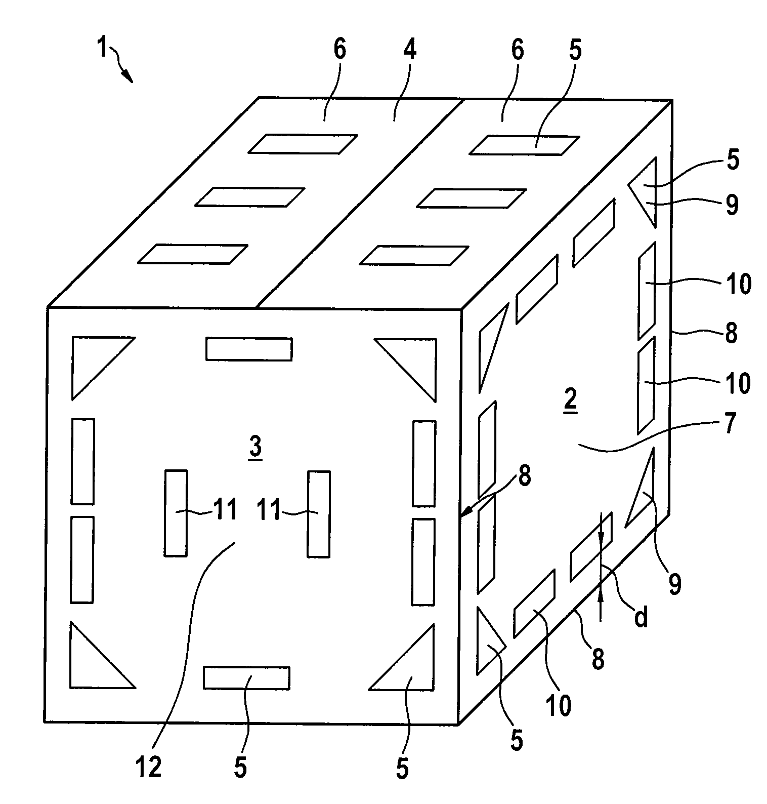
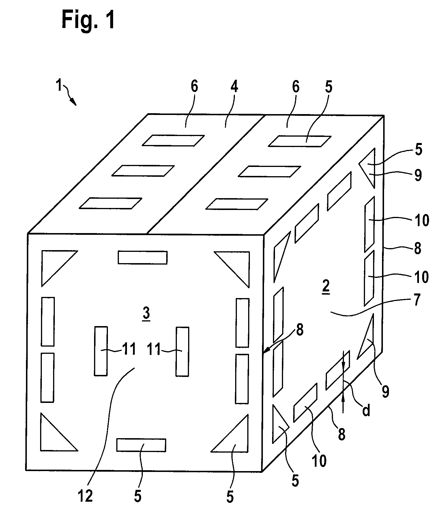
[0048]A container according to the present invention with an outer container according to FIG. 1 and an inner container according to FIG. 2 was tested. The inner container was made of polystyrene with the outer dimensions 715×580×640 mm3 including the ribs and had ribs of 10 mm height and 10 mm width arranged on its outer surface. The specific foam weight of the polystyrene was 20 g/l. The outer container was a cardboard box with a plurality of ventilation holes with the outer dimensions 736×597×673 mm3 (quality 2.60 BC). Two tests were carried out with the container according to the invention, the first test within a cold-storage container with an inside temperature of 3.5 to 4° C. and the second test within a room of about 20° C. In both tests the container was filled with 30 kg of dry ice (with a temperature of −78.5° C.). A smaller cardboard box filled with 17 sample packages was placed successively in contact with a) a long side of the container, b) a narrow side of the container, and c) the cover of the container, allowing heat energy to be transferred from the actually contacting walls of the smaller cardboard box to the outer surface of the container according to the invention. The sample packages were filled with diagnostic kits, which hade a temperature between 2° C. and 8° C., when they were placed in the smaller cardboard box. A temperature recorder was connected to the inside of the wall of the smaller cardboard box, which touched the container at its outside.
[0049]In test 1 (surrounding temperature of 3.4 to 4° C.) the inner wall of the smaller cardboard box adapted a temperature of 0° C. to 1° C. in all three different arrangements a) to c) within the first 2 days. In test 2 (surrounding temperature of about 20° C.) the inner wall of the smaller cardboard box adapted a temperature of a) 12° C. to 18° C., b) 12° C. to 17° C. and c) 9° C. to 17° C. within the first 2 days.
[0050]Therefore, in both tests the inside of the smaller cardboard box was only cooled down by a few degrees Celsius. Particularly, it was not cooled down below the freezing point. The container according to the invention was thus capable of preventing an unwanted cooling of freezing of neighboring goods via its outer surface.

PUM

PropertyMeasurementUnit
Height0.01m
Height0.03m
Thermal insulator

Description & Claims & Application Information

We can also present the details of the Description, Claims and Application information to help users get a comprehensive understanding of the technical details of the patent, such as background art, summary of invention, brief description of drawings, description of embodiments, and other original content. On the other hand, users can also determine the specific scope of protection of the technology through the list of claims; as well as understand the changes in the life cycle of the technology with the presentation of the patent timeline. Login to view more.

Similar technology patents

Process and arrangement for producing tetrahydrofuran

InactiveUS6204399B1expenditure for such can be reduceavoids disadvantage
Owner:LINDE AG

System and method for generating three-dimensional image displays

ActiveUS7098458B2avoids disadvantage
Owner:CARL ZEISS OPTRONICS GMBH NEW NAME

Classification and recommendation of technical efficacy words

  • avoids disadvantage

Endoprosthesis for a shoulder joint

InactiveUS6749637B1avoids disadvantage
Owner:BAHLER OLGA MARIA

Stent

Owner:BIOTRONIK MESTRASSE UND THERAPIEGERATE GMBH & CO ING BERLIN

Electronic Device Case with Changeable Panel

ActiveUS20130257240A1additional operating advantageavoids disadvantage
Owner:UNCOMMON

Two-Piece Protective Carrying Case

ActiveUS20110049005A1avoids disadvantageadditional structural and operating advantage
Owner:UNCOMMON

Exercise Device

InactiveUS20090112137A1avoids disadvantage
Owner:LAMORE GEORGE
Why Eureka
Try Eureka