
Transmission mount for car

a technology for transmission mounts and vehicles, applied in mechanical devices, shock absorbers, transportation and packaging, etc., can solve the problems of increasing user fatigue, affecting the lifetime of parts of the vehicle, and affecting the operation of the vehicle, so as to prevent the vehicle from being disassembled and reduce vibration and noise. , the effect of effective reduction

Inactive Publication Date: 2009-04-16
DTR
View PDF12 Cites 3 Cited by
  • Summary
  • Abstract
  • Description
  • Claims
  • Application Information

AI Technical Summary

Benefits of technology

[0010]Accordingly, the present invention has been made to solve the above-mentioned problems occurring in the prior art, and the present invention provides a transmission mount for a vehicle, which can minimize the amount of displacement respective to a transmission.
[0011]Also, the present invention provides a transmission mount for a vehicle, which can be prevented from escaping from a transmission or being damaged when a side collision of a vehicle occurs in an accident.
[0018]As described above, according to the present invention, by minimizing the amount of displacement of a transmission mount respective to a transmission for a vehicle, vibration and noise generated in operating a vehicle can be effectively reduced.
[0019]Also, a transmission mount can be prevented from being disassembled from a transmission or from being damaged in a side collision of a vehicle occurs in an accident.

Problems solved by technology

Vibration and noise due to the vibration, which are generated during operation of a vehicle, increase fatigue of a user, and have an effect on the lifetime of parts of the vehicle.
However, such a conventional transmission mount can be displaced respective to the transmission when the vehicle is driven.
Therefore, the conventional transmission mount cannot effectively absorb the vibration of the vehicle.

Method used


Image

  • Transmission mount for car
  • Transmission mount for car
  • Transmission mount for car

Examples


Embodiment Construction

[0027]Hereinafter, an exemplary embodiment of the present invention will be described with reference to the accompanying drawings.

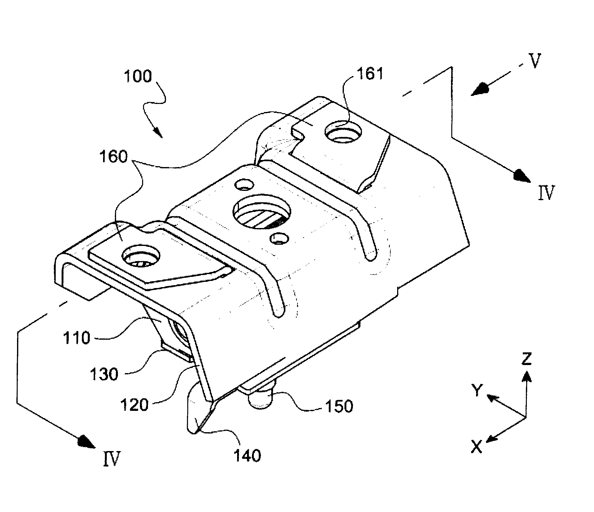
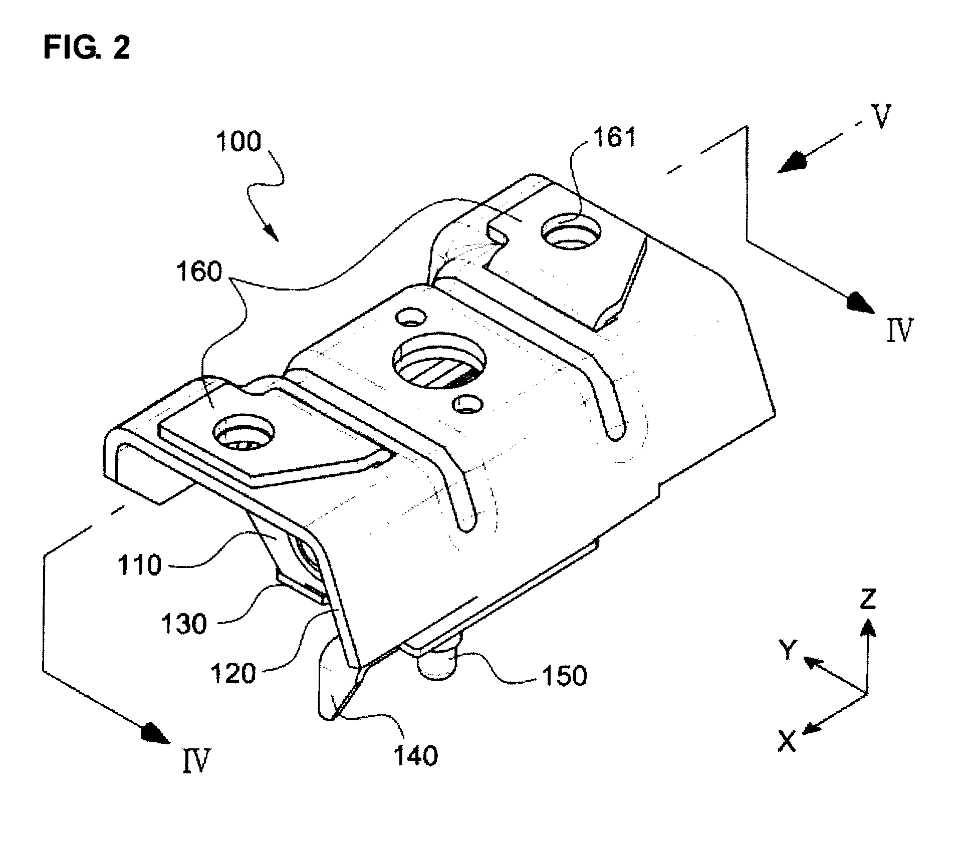
[0028]As shown in FIGS. 2 and 4, a transmission mount 100 for a vehicle according to the present invention includes a vibration isolation member 110, an upper plate 120, a lower plate 130, a spacer 140, a chassis bolt 150, a pair of support brackets 160 having each bracket assembling hole 161, and a bracket supporting pin 170.

[0029]According to an embodiment of the present invention, vibration isolation member 110 preferably includes rubber.

[0030]As shown in FIG. 3, the upper plate 120 is assembled with an upper portion of the vibration isolation member 110 while surrounding an upper portion of the vibration isolation member 110. The upper plate 120 includes slots 123, a vibration absorber injecting hole 121 formed at the center of the surface thereof, and assembling holes 122 formed on the surface of the upper plate symmetrically to each other, base on t...


PUM


Abstract

Disclosed is a transmission mount for a vehicle, which includes a vibration isolation member; an upper plate assembled with an upper portion of the vibration isolation member so as to surround the upper portion of the vibration isolation member; a lower plate assembled with a lower portion of the vibration isolation member so as to surround the lower portion of the vibration isolation member; and a pair of supporting brackets assembled on a surface of the upper plate in such a manner that the supporting brackets are symmetrical to each other so as to support the upper plate. Accordingly, the amount of displacement of the transmission mount according to the vibration of a vehicle can be minimized.

Description

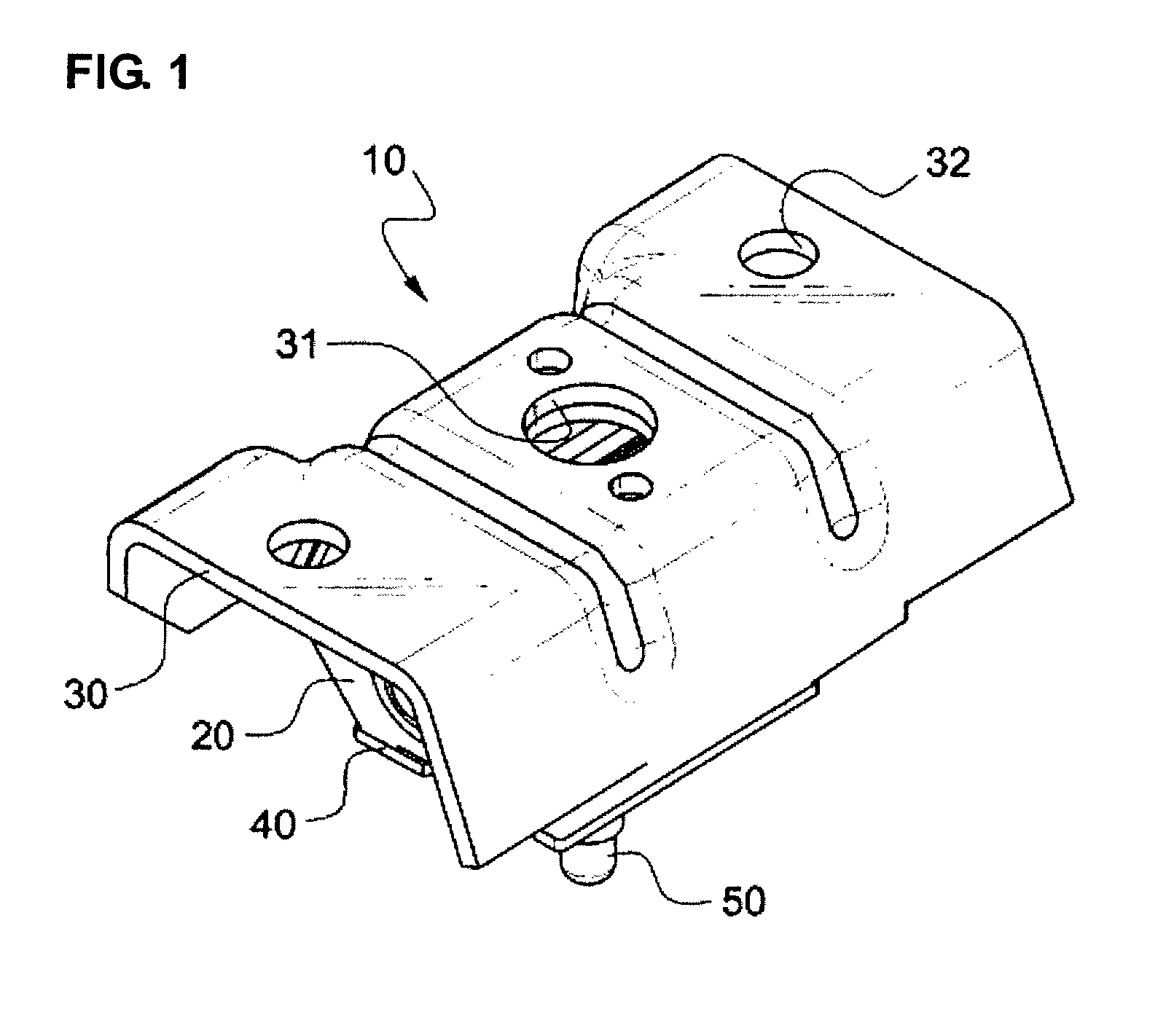
BACKGROUND OF THE INVENTION[0001]1. Field of the Invention[0002]The present invention relates to a transmission mount for a vehicle, and more particularly to a transmission mount for a vehicle, which has an improved structure allowing vibration of a vehicle to be reduced.[0003]2. Description of the Prior Art[0004]Vibration and noise due to the vibration, which are generated during operation of a vehicle, increase fatigue of a user, and have an effect on the lifetime of parts of the vehicle.[0005]In order to reduce such vibration of a vehicle, a transmission mount as a vibration isolation damper is mounted between a transmission and a chassis of the body of a vehicle.[0006]As shown in FIG. 1, a conventional transmission mount 10 includes a vibration isolation member 20, an upper plate 30 assembled with the upper portion of the vibration isolation member 20 so as to surround the vibration isolation member 20, a lower plate 40 assembled with the lower portion of the vibration isolation...

Claims


Application Information

Patent Timeline
IPC IPC(8): F16F7/00
CPCF16F2230/007F16F1/3713B60K17/06
Inventor KIM, JAE HEON
Owner DTR
Learn More