Image-capturing device, camera, method for constructing image-capturing device and image-capturing method

Active Publication Date: 2009-04-16
NIKON CORP
View PDF11 Cites 53 Cited by
  • Summary
  • Abstract
  • Description
  • Claims
  • Application Information

AI Technical Summary

Benefits of technology

[0007]However, when the display of live view and the focus detection operation are executed simultaneously by the above-mentioned conventional imaging apparatus, there is the possibility that outputs of different types of pixels will be mixed at the time of addition. If the outputs of the imaging pixels and the focus detection pixels are mixed at the time of addition, or outpu

Problems solved by technology

If the outputs of the imaging pixels and the focus detection pixels are mixed at the time of addition, or outputs of different types of imaging pixels are mixed at the time of addition, there is the possibility that quality of the displayed image based on the added pixel data will be deteriorated.
Further, if the outputs of different types of focus detection pixels are mixed at the time of addition, there is the possibility that focus detection using added pixel data cannot be executed.

Method used


Image

  • Image-capturing device, camera, method for constructing image-capturing device and image-capturing method
  • Image-capturing device, camera, method for constructing image-capturing device and image-capturing method
  • Image-capturing device, camera, method for constructing image-capturing device and image-capturing method

Examples


first embodiment

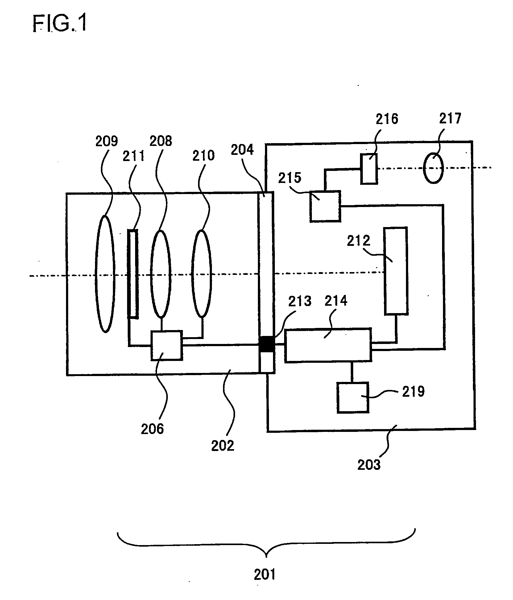
[0085]A digital still camera used in conjunction with exchangeable lenses, representing an example of an imaging apparatus equipped with the focus detector achieved in an embodiment of the present invention is now explained. FIG. 1 is a lateral sectional view of the structure adopted in the camera in the embodiment. A digital still camera 201 achieved in the embodiment includes an exchangeable lens 202 and a camera body 203. The exchangeable lens 202 is mounted at the camera body 203 via a mount unit 204.

[0086]The exchangeable lens 202 includes a lens 209, a zooming lens 208, a focusing lens 210, an aperture 211, a lens drive controller 206 and the like. The lens drive controller 206 is constituted with a microcomputer, a memory, a drive control circuit and the like (not shown). The lens drive controller 206 engages in communication with a body drive controller 214 to be detailed later to transmit lens information to the body drive controller 214 and receive camera information from ...

second embodiment

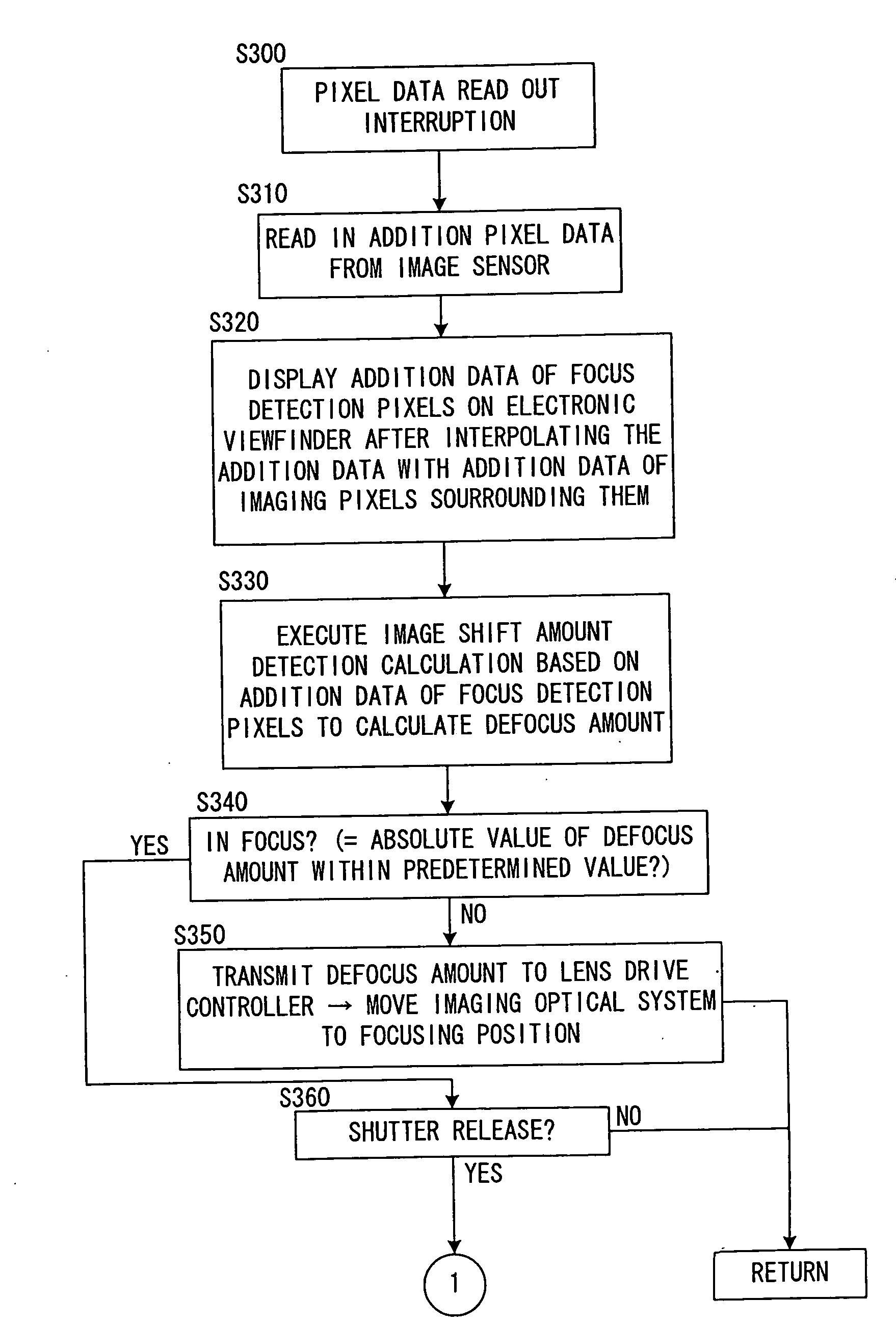
[0144]According to the First Embodiment, as shown in FIG. 3, the two types of focus detection pixels 313 and 314 are disposed alternately along the direction of row. The pixel addition operation is executed by adding signals from two pixels, i.e., every other pixels s in the same row so as to prevent mixing of signals from the two types of the focus detection pixels 313 and 314 at the time of pixel addition, thus enabling the addition pixel signals to be used in focus detection calculation. The positional relationship between the pattern in which the focus detection pixels are disposed and the plurality of pixels used for the addition of pixels (addition pattern) is not limited to the one described in the First Embodiment and various modifications can be conceived.

[0145]FIG. 19 is a front view showing in detail the structure adopted in an image sensor 212A achieved in a variation. It is to be noted that FIG. 19 shows the vicinity of the focus detection area 100 set on the image sens...


PUM


Abstract

An image-capturing device includes: a plurality of first pixels disposed along a first direction; a plurality of second pixels different from the first pixels disposed along the first direction in admixture with the plurality of first pixels; and an adder that adds a plurality of outputs provided by a plurality of first selected pixels selected from the plurality of first pixels to each other and a plurality of outputs provided by a plurality of second selected pixels selected from the plurality of second pixels to each other in such a manner that outputs provided by the first pixels and outputs provided by the second pixels are not added one to another. Disposition of the plurality of second pixels conforms to positional relationship of the plurality of first selected pixels in the plurality of first pixels.

Description

INCORPORATION BY REFERENCE[0001]The disclosures of the following priority applications are herein incorporated by reference: Japanese Patent Application No. 2007-257409 filed Oct. 1, 2007, and U.S. Provisional Patent Application No. 60 / 960,518, Oct. 2, 2007.BACKGROUND OF THE INVENTION[0002]1. Field of the Invention[0003]The present invention relates to an image-capturing device, camera, method for constructing image-capturing device and image-capturing method.[0004]2. Description of Related Art[0005]Japanese Laid Open Patent Application No. 2007-155929 discloses an imaging device that includes an image sensor having two-dimensionally arrayed imaging pixels a portion of which is substituted by one or more focus detection pixels, the image sensor being used to perform imaging and focus detection.[0006]There is an imaging apparatus known in the art that displays a live view by repeating operations of adding outputs of imaging pixels and displaying the result as an output of display pix...

Claims


Application Information

Patent Timeline
IPC IPC(8): H04N5/228H04N5/232G02B7/28G02B7/34G03B13/36H01L27/146H04N5/335H04N5/347H04N5/357H04N5/369H04N5/374
CPCH04N5/23293H04N5/23212H04N23/672H04N23/63H04N25/704H04N23/843H04N25/134
Inventor KUSAKA, YOSUKE
Owner NIKON CORP
Why Eureka
Try Eureka