Display device, driving method thereof, terminal device, and display panel

a technology of display panel and driving method, which is applied in the direction of semiconductor devices, instruments, optics, etc., can solve the problems of difficult to improve numerical aperture with the conventional pixel structure, and so as to reduce the influence of abnormal alignment, improve the quality of display image at the corresponding observation position, and improve the effect of image quality

Active Publication Date: 2009-04-16
NEC LCD TECH CORP
View PDF3 Cites 73 Cited by
  • Summary
  • Abstract
  • Description
  • Claims
  • Application Information

AI Technical Summary

Benefits of technology

[0019]With this, the neighboring pixel pairs of different structures can be arranged. Thus, it is possible to decrease influences of abnormal alignment of the liquid crystal molecules if it happens. This is because it is possible to prevent the abnormal state from generating at same positions of the whole pixels, since the positions of having abnormal alignment or the like differ when the pixel structures vary. Especially, the plural-viewpoint display device according to the exemplary embodiment of the present invention enlarges the images by using the image separating device such as a lens. Therefore, when the abnormal state occurs at the same positions of the whole pixels, the display image quality at the corresponding observing position becomes deteriorated. Through arranging the neighboring pixel pairs of different structures, the positions at which the deteriorated display image is observed can be dispersed. This makes it possible to improve the display quality.

Problems solved by technology

However, the techniques described above have following issues.
That is, for increasing the display qualities while using thin film transistors, it is difficult with the conventional pixel structure to improve the numerical aperture while maintaining the above-described aperture shape.

Method used


Image

  • Display device, driving method thereof, terminal device,  and display panel
  • Display device, driving method thereof, terminal device,  and display panel
  • Display device, driving method thereof, terminal device,  and display panel

Examples


Embodiment Construction

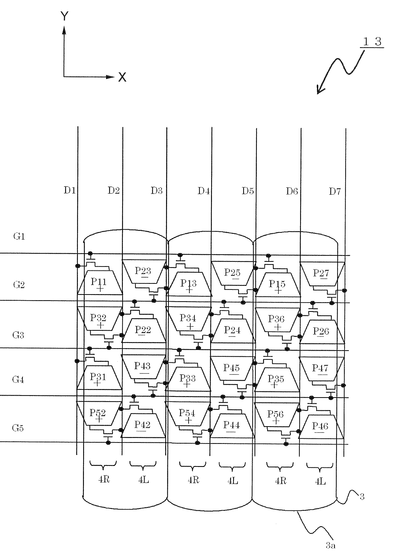
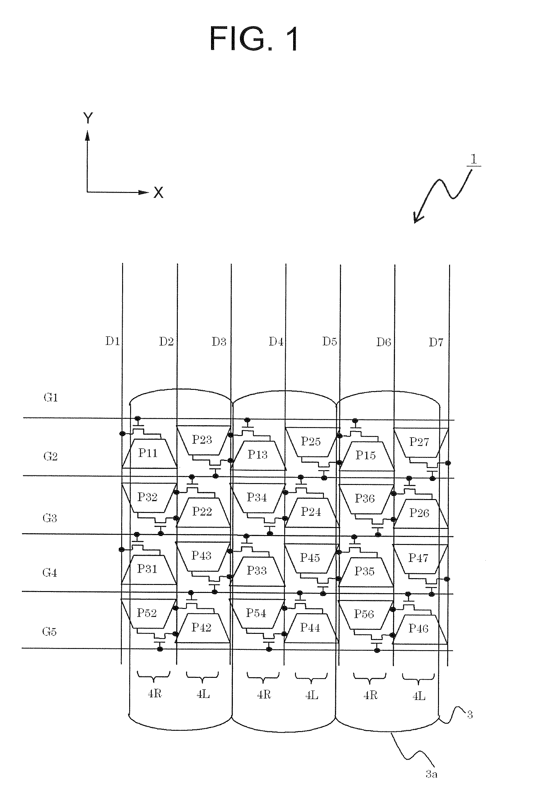
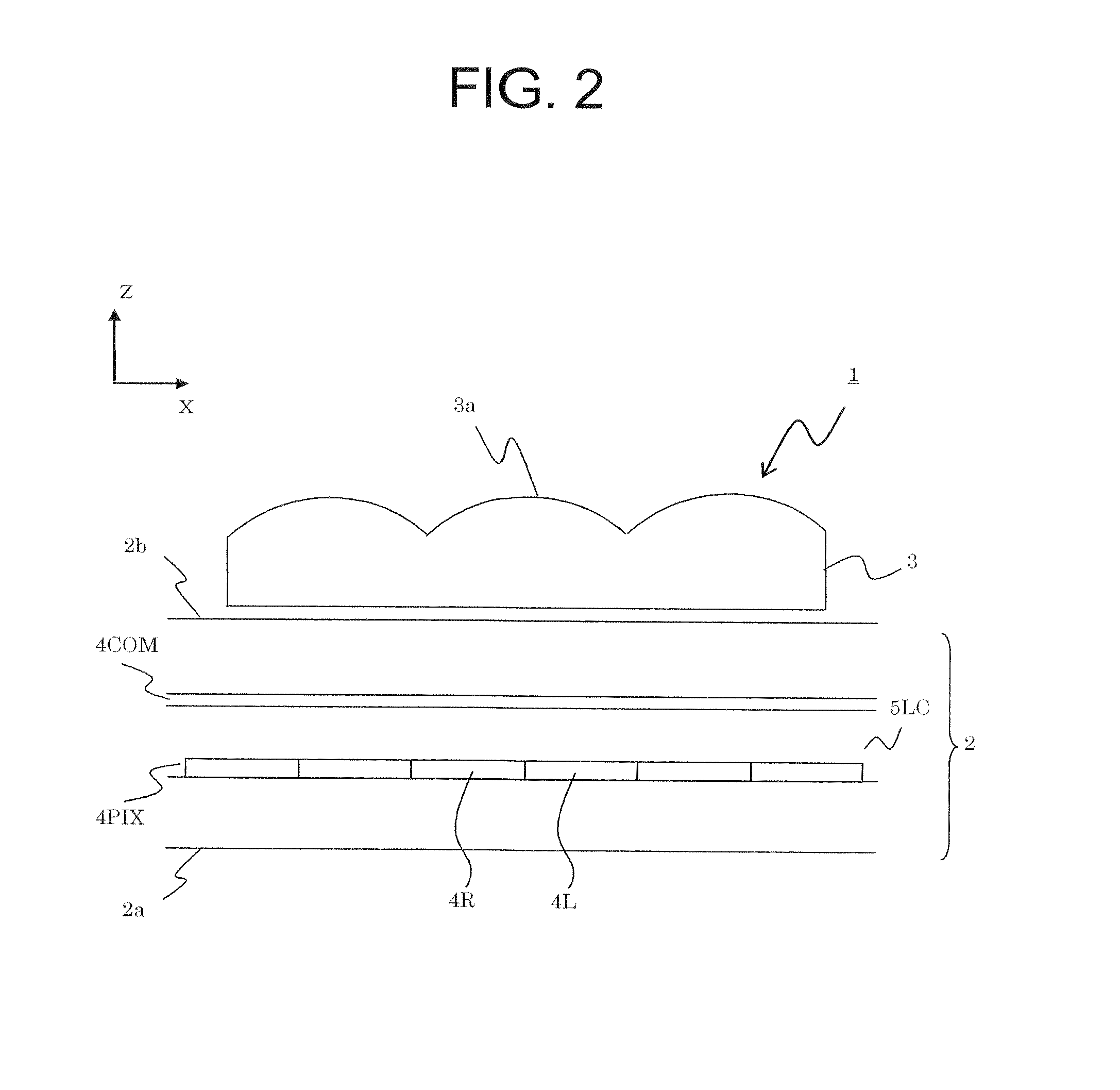
[0054]Hereinafter, a display device, its driving method, a terminal device, and a display panel according to exemplary embodiments of the present invention will be described in a concrete manner by referring to the accompanying drawings. First, the display device, its driving method, the terminal device, and the display panel according to a first exemplary embodiment of the present invention will be described. FIG. 1 is a top plan view showing the display device according to the first exemplary embodiment of the present invention, which, in particular, shows a relation between electrical connection of pixels and a lenticular lens as an image separating device. FIG. 2 is a sectional view showing the display device according to this exemplary embodiment. FIG. 3 is a top plan view showing pixels of the display device according to this exemplary embodiment, and FIG. 4 is a perspective view showing a terminal device according to this exemplary embodiment.

[0055]As shown in FIG. 1 and FIG....


PUM

PropertyMeasurementUnit
refractive indexaaaaaaaaaa
ODaaaaaaaaaa
distance WPaaaaaaaaaa

Abstract

To provide a plural-viewpoint display device having an image separating optical element such as a lenticular lens or a parallax barrier, which is capable of arranging thin film transistors and wirings while achieving substantially trapezoid apertures and high numerical aperture, and to provide a driving method thereof, a terminal device, and a display panel. A neighboring pixel pair arranged with a gate line interposed therebetween is connected to the gate line placed between the pixels, each of the pixels configuring the neighboring pixel pair is connected to the data line different from each other, and each of the neighboring pixel pairs neighboring to each other in an extending direction of the gate lines is connected to the gate line different from each other.

Description

CROSS-REFERENCE TO RELATED APPLICATION[0001]This application is based upon and claims the benefit of priority from Japanese patent application No. 2007-268423, filed on Oct. 15, 2007, the disclosure of which is incorporated herein in its entirety by reference.BACKGROUND OF THE INVENTION[0002]1. Field of the Invention[0003]The present invention relates to a display device capable of displaying an image to each of a plurality of viewpoints, its driving method, a terminal device, and a display panel. More specifically, the present invention relates to a display device capable of providing high quality display, its driving method, a terminal device, and a display panel.[0004]2. Description of the Related Art[0005]Owing to the recent technical developments, display panels are used in various places by being loaded not only to large-scale terminal devices such as monitors and television receiver sets but also to medium-scale terminal devices such as notebook-type personal computers, cash ...

Claims


Application Information

Patent Timeline
Patent Type & Authority Applications(United States)
IPC IPC(8): G02F1/133G02F1/1343G02B30/27G02B30/30
CPCG02B27/2214G02F1/13624G02F1/133512G02F1/133526G02F1/134309G02F1/136213G02F1/136286G02F2201/122G02F2201/40H04N13/0404H04N13/0409H04N13/0447H04N13/0497H04N2213/001G09G5/003G02F1/134363G02B27/2264H04N13/305H04N13/31H04N13/351H04N13/398G02B30/24G02B30/27G02B30/30G09G3/3611G09G3/2003G09G3/3648G09G2320/02G09G2320/10G02F1/1362G02F1/1343G02F1/134336G02F1/136222G02F1/136227G02F1/1368H01L27/1222
Inventor UEHARA, SHINICHIIKENO, HIDENORISATOU, TETSUSHI
Owner NEC LCD TECH CORP
Why Eureka
Try Eureka