Stereoscopic image display apparatus and method of manufacturing the same

a technology of stereoscopic image and display apparatus, which is applied in the manufacture of electrode systems, electric discharge tubes/lamps, instruments, etc., can solve the problems of deterioration in the quality of a displayed image, uneven distance between the image display panel b>51/b> and the phase difference element b>52/b>, and insufficient adhesion near a central location, so as to avoid deterioration in the quality of the displayed image, reduce contras

Inactive Publication Date: 2010-02-04
SONY CORP
View PDF67 Cites 9 Cited by
  • Summary
  • Abstract
  • Description
  • Claims
  • Application Information

AI Technical Summary

Benefits of technology

[0012]Accordingly, it is desirable to provide a stereoscopic image display apparatus which can properly bond a phase difference element to an image display panel over an entire panel surface even when there are projections and depressions formed by light shield layers, and to provide a method of manufacturing the stereoscopic image display apparatus.
[0013]According to an embodiment of the present invention, a stereoscopic image display apparatus includes an image display panel displaying an image for a right eye and an image for a left eye in a regularly mixed manner in a plane, a phase difference element including a right-eye image display portion corresponding to the image for the right eye and a left-eye image display portion corresponding to the image for the left eye, the right-eye image display portion and the left-eye image display portion bringing about polarization such that the image for the right eye and the image for the left eye have different polarization states, a light shield layer formed only in an area including a boundary between the right-eye image display portion and the left-eye image display portion of the phase difference element, the light shield layer projecting toward the image display panel, and a binder layer interposed between the surface of the phase difference element on which the light shield layer is formed and the image display panel to levelly coat and fill projections and recesses formed by the light shield layers, thus bonding the image display panel, the phase difference element, and the light shield layers together.
[0014]In the stereoscopic image display apparatus thus constructed, the binder layer is interposed between the image display panel 1 and the phase difference element, including the light shield layers, in such a manner that the projections and the recesses formed by the light shield layers are levelly coated and filled with the binder layer, thus bonding the image display panel and the phase difference element 2, etc. together. Even with the projections and the recesses formed on the surface of the phase difference element by the light shield layers, therefore, the binder layer is filled in a way following respective shapes of the projections and the recesses formed by the light shield layers to prevent an air layer from being generated by the absence of the binder layer. Thus, even with the light shield layers providing the projections and the recesses, the generation of an air layer possibly causing deterioration in quality of a displayed image can be prevented, whereby the image display panel and the phase difference element can be bonded to each other over an entire panel surface.
[0016]With the embodiment of the present invention, since the image display panel and the phase difference element are bonded to each other over the entire panel surface, it is possible to prevent generation of, e.g., the Moiré phenomenon or the Newton rings (interference fringes), which may cause deterioration in quality of the displayed image.
[0017]In addition, in spite of the projections and the recesses being formed by the light shield layers, since the binder layer is interposed so as to levelly coat and fill the projections and the recesses, an air layer is prevented from being generated due to the absence of the binder layer. It is therefore possible to avoid deterioration in quality of the displayed image, such as unsatisfactory uniformity and reduction of contrast of the displayed image, which are attributable to the presence of the air layer.
[0018]Thus, in constructing the stereoscopic image display apparatus according to the embodiment of the present invention, even when the projections and the recesses are formed by the light shield layers, the phase difference element and the light shield layer can be properly bonded to the image display panel.

Problems solved by technology

However, when the image display panel 51 and the phase difference element 52 are fixed to each other only at the outer peripheral portion, there is a risk that sufficient adhesion is not provided near a central portion of a display area, or that the distance between the image display panel 51 and the phase difference element 52 becomes uneven.
Such a problem regarding the insufficient adhesion or the uneven distance, for example, is to be avoided because the problem may generate, e.g., the Moiré phenomenon or the Newton rings (interference fringes), and may cause deterioration in quality of a displayed image.
An air layer generated as a result of the binder not spreading into every corners may impair uniformity or reduce contrast of the displayed image, for example, due to the light refractive action at the air layer, thus causing deterioration in quality of the displayed image.

Method used


Image

  • Stereoscopic image display apparatus and method of manufacturing the same
  • Stereoscopic image display apparatus and method of manufacturing the same
  • Stereoscopic image display apparatus and method of manufacturing the same

Examples


Embodiment Construction

[0025]A stereoscopic image display apparatus and a method of manufacturing the stereoscopic image display apparatus, according to an embodiment of the present invention, will be described below with reference to the drawings.

[Basic Construction of Stereoscopic Image Display Apparatus]

[0026]A basic construction of the stereoscopic image display apparatus is first described.

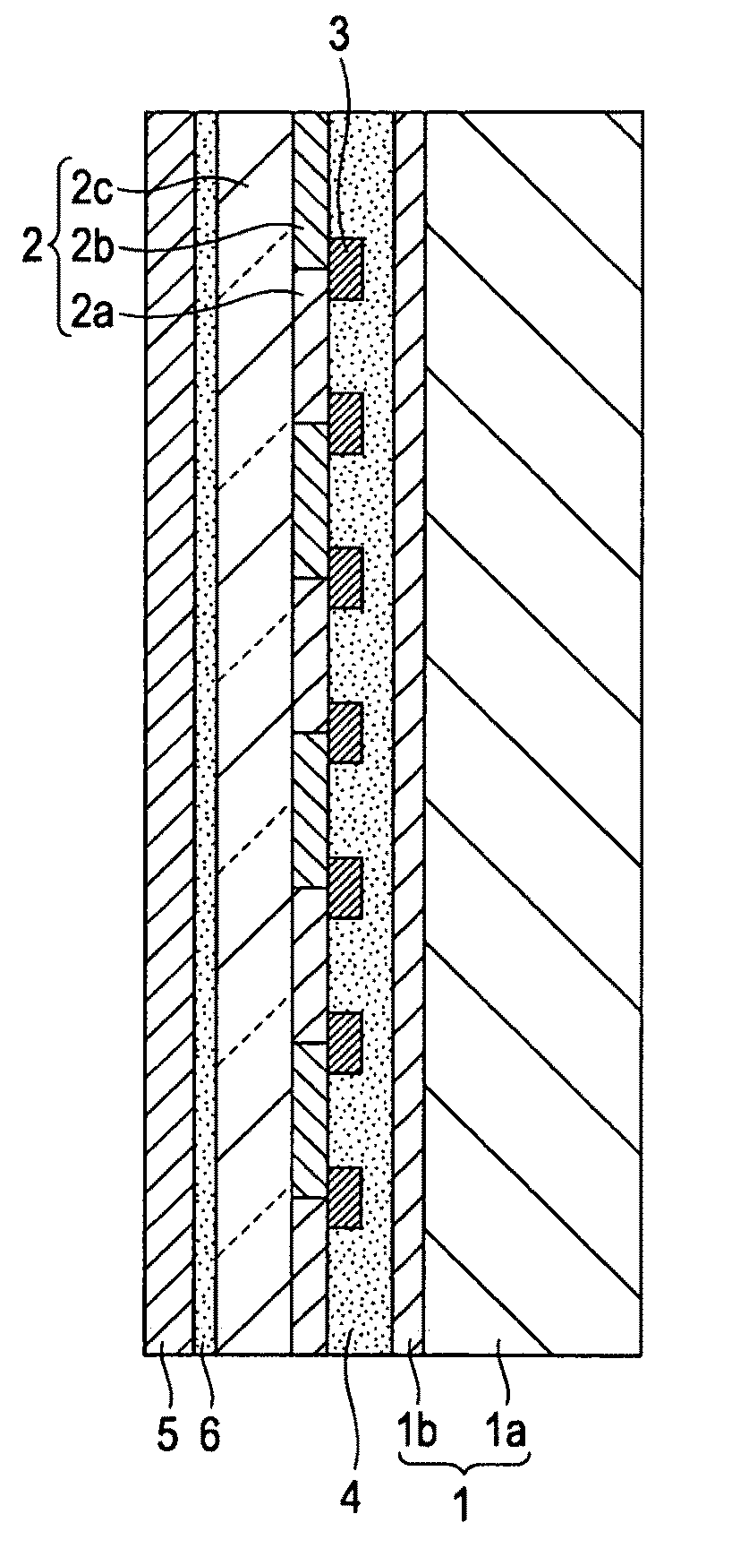
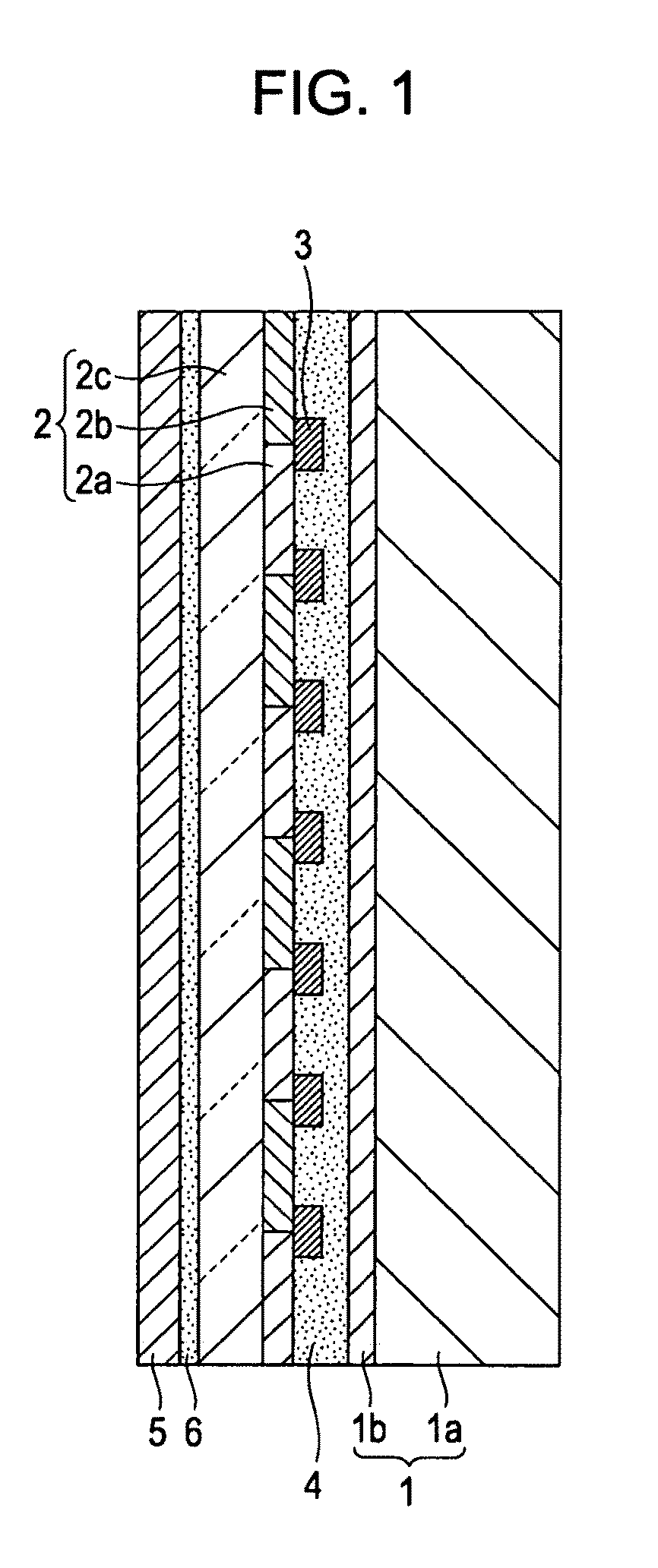
[0027]FIG. 1 is an explanatory view illustrating a first example of construction, in a simplified form, of the stereoscopic image display apparatus according to the embodiment of the present invention.

[0028]The stereoscopic image display apparatus, illustrated in FIG. 1, includes an image display panel 1, a phase difference element 2, a light shield layer 3, a binder layer 4, an antireflective film 5, and a binder layer 6.

[0029]The image display panel 1 includes at least a liquid crystal panel 1a and a polarizing plate 1b arranged on an image output surface side of the liquid crystal panel 1a. The image display pan...


PUM


Abstract

A stereoscopic image display apparatus includes an image display panel displaying an image for a right eye and an image for a left eye in a regularly mixed manner in a plane, a phase difference element including a right-eye image display portion corresponding to the image for the right eye and a left-eye image display portion corresponding to the image for the left eye to provide different polarization states, a light shield layer formed to project only in an area including a boundary between the right-eye image display portion and the left-eye image display portion of the phase difference element, and a binder layer interposed between the phase difference element and the image display panel to levelly coat and fill projections and recesses formed by the light shield layers, thus bonding the image display panel, the phase difference element, and the light shield layers together.

Description

CROSS-REFERENCE TO RELATED APPLICATION[0001]The present application claims priority from Japanese Patent Application No. JP 2008-193101 filed in the Japanese Patent Office on Jul. 28, 2008, the entire content of which is incorporated herein by reference.BACKGROUND OF THE INVENTION[0002]1. Field of the Invention[0003]The present invention relates to a stereoscopic image display apparatus for displaying a stereoscopic image by utilizing an image for a right eye and an image for a left eye, and also relates to a method of manufacturing the stereoscopic image display apparatus.[0004]2. Description of the Related Art[0005]Hitherto, a stereoscopic image display apparatus for displaying a stereoscopic image has been proposed, for example, which is constructed as illustrated in FIG. 6 (see, e.g., Japanese Unexamined Patent Application Publication No. 2002-196281). The stereoscopic image display apparatus, illustrated in FIG. 6, includes an image display panel 51 made of a liquid crystal pan...

Claims


Application Information

Patent Timeline
Patent Type & Authority Applications(United States)
IPC IPC(8): H04N13/04H01J9/24G02B30/25
CPCG03B35/18
Inventor SAKATA, ATSUSHIABE, HIROMICHINIYOMURA, HIDEOKARASAWA, JOJIOKADA, MASAMICHIKOBAYASHI, TAKAYUKIHORIE, OSAMUOHNO, HIROSHI
Owner SONY CORP
Why Eureka
Try Eureka