This helps you quickly interpret patents by identifying the three key elements:
Problems solved by technology
Method used
Benefits of technology
Benefits of technology
[0006]Adverse effects of spinal surgery, such as ASD and other complications, can be alleviated to a large extent by assemblies for dynamic stabilization of the spine, in accordance with the present invention.
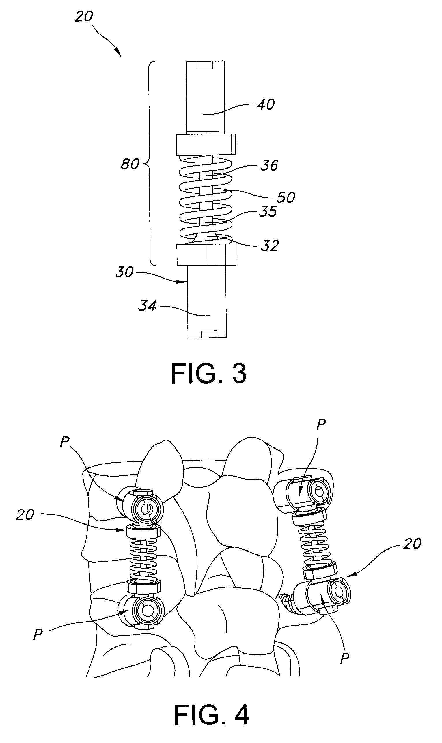
[0007]In a first aspect of the invention, an assembly for dynamic stabilization of the spine includes a rod having a first end with a first diameter and a second end with a second diameter smaller than the first diameter. A hollow housing forms a passage that receives the second end of the rod. An elastic member connects the first end of the rod with the housing.
[0008]In a second aspect of the invention, an assembly for dynamic stabilization of the spine includes a rod having a first end with a first diameter and a second end with a second diameter smaller than the first diameter. A hollow housing forms a passage that receives the second end of the rod. An elastic member connects
Problems solved by technology
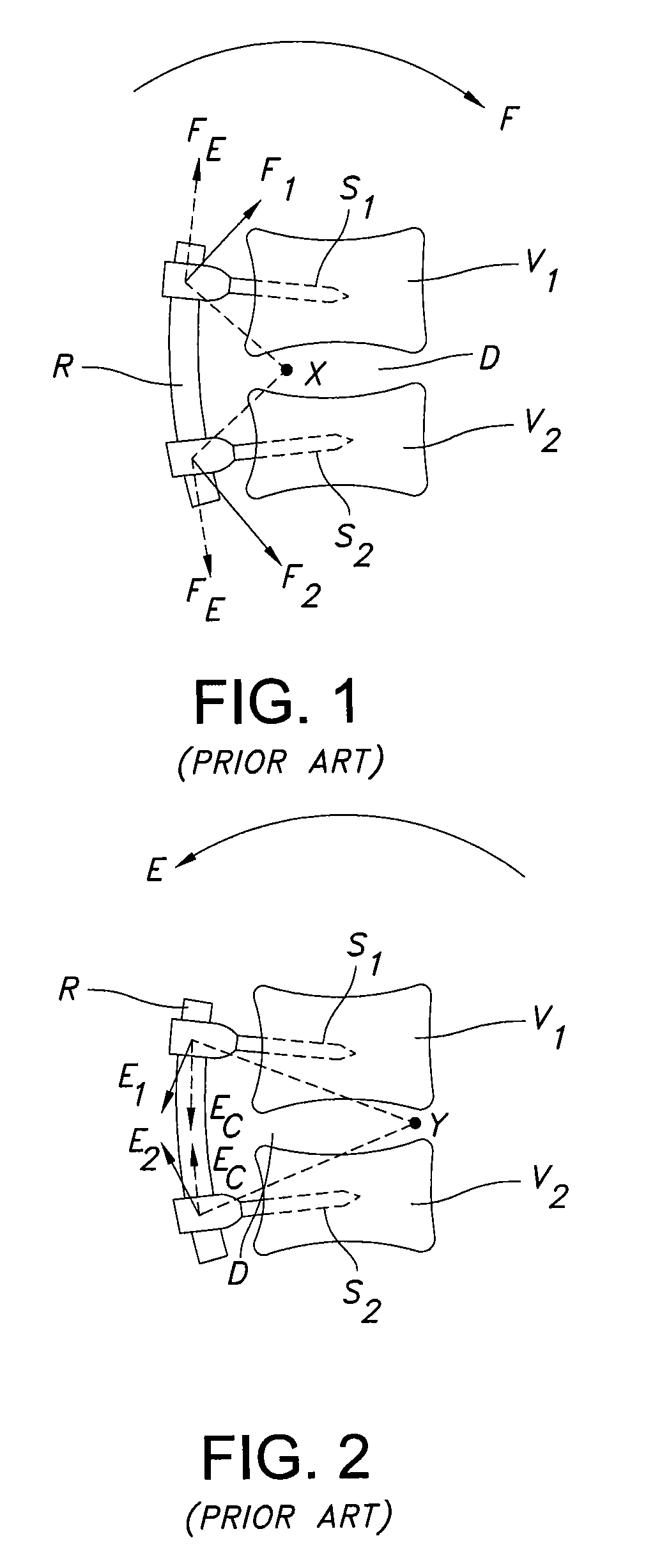
Nevertheless, spinal fusion can create or exacerbate other problems, including damage to nearby discs.
Because a fused joint cannot bend, the spine loses mobility at that joint.
This can cause the nearby disc joints to become damaged or degenerate at an accelerated rate, leading to complications and the need for more surgeries.
A biomechanical analysis of the performance of these rods demonstrates that this perception is not true, and that solid flexible rods have the unexpected result of constraining motion.
Method used
Image
Click on the blue label to locate the original text in one second.
Reading with bidirectional positioning of images and text.
Examples
first embodiment
[0038]In a first embodiment, an assembly for dynamic stabilization of the spine includes:
[0039]a rod comprising a first end having a first diameter and a second end having a second diameter smaller than the first diameter;
[0040]a hollow housing forming a passage that receives the second end of the rod; and
[0041]an elastic member connecting the first end of the rod with the housing.
second embodiment
[0042]In a second embodiment, an assembly for dynamic stabilization of the spine includes:
[0043]a rod comprising a first end having a first diameter and a second end having a second diameter smaller than the first diameter;
[0044]a hollow housing forming a passage that receives the second end of the rod;
[0045]an elastic member connecting the first end of the rod with the housing;
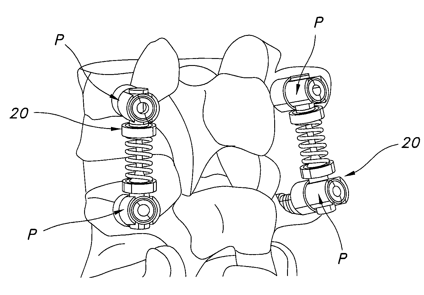
[0046]a first pedicle screw having a rod receiving slot, the first end of the rod being supported in the rod receiving slot of the first pedicle screw; and
[0047]a second pedicle screw having a rod receiving slot, the housing being supported in the rod receiving slot of the second pedicle screw.
third embodiment
[0048]In a third embodiment, an assembly for dynamic stabilization of the spine includes:
[0049]a rod having a longitudinal axis, the rod comprising:[0050]a first end having a first diameter; and[0051]a second end having a second diameter smaller than the first diameter; and
[0052]a sleeve coupled to the rod that circumscribes at least a portion of the second end of the rod, the sleeve comprising:[0053]a cylindrical housing; and[0054]an elastic section connected between the cylindrical housing and the first end of the rod, the elastic section being expandable parallel to the longitudinal axis of the rod.
[0055]The use of separate independent components provides a controlled flexibility that is not available with assemblies that feature a single homogeneous element, such as a solid flexible rod. When a solid rod is connected to two adjacent vertebrae by pedicle screws, bending motion between the vertebrae often requires axial expansion and contraction of the rod. Bending of the spine of...
PUM
Abstract
An assembly for dynamic stabilization of the spine includes a rod having a first end having a first diameter and a second end having a second diameter smaller than the first diameter. A hollow housing forms a passage that receives the second end of the rod. An elastic member connects the first end of the rod with the housing. The assembly includes or is operable with a first pedicle screw and a second pedicle screw, each pedicle screw having a rod receiving slot. The first end of the rod is supported in the rod receiving slot of the first pedicle screw, and the housing is supported in the rod receiving slot of the second pedicle screw.
Description
RELATED APPLICATIONS[0001]This non-provisional application claims the benefit of priority to U.S. Provisional Application No. 60 / 979,489, filed Oct. 12, 2007, the entire contents of which are incorporated by reference herein for all purposes.FIELD OF THE INVENTION[0002]The present invention relates generally to treatment of the spine, and more particularly to a method and apparatus for dynamic stabilization of the lumbar spine.BACKGROUND[0003]Historically, spinal fusion was the surgical therapy of choice for patients with spine disorders. Spinal fusion involves the replacement of the intervertebral disc with a bone graft and often posterior fixation using bone screws and solidtitanium rods. The stabilization provided by the screws allows the bone graft to grow between the two vertebrae. This fuses the vertebrae together as one solid piece of bone.[0004]Spinal fusion is capable of providing local stability at the motion segment to relieve pain. Nevertheless, spinal fusion can create...
Claims
Application Information
Patent Timeline
Application Date:The date an application was filed.
Publication Date:The date a patent or application was officially published.
First Publication Date:The earliest publication date of a patent with the same application number.
Issue Date:Publication date of the patent grant document.
PCT Entry Date:The Entry date of PCT National Phase.
Estimated Expiry Date:The statutory expiry date of a patent right according to the Patent Law, and it is the longest term of protection that the patent right can achieve without the termination of the patent right due to other reasons(Term extension factor has been taken into account ).
Invalid Date:Actual expiry date is based on effective date or publication date of legal transaction data of invalid patent.

