Device and Method for Designing a Garment

a computer-aided design and garment technology, applied in the field of computer-aided design of garments, can solve the problems of inability to reproduce the constraints defined by pattern designers or patterners, methods that place stringent limitations on the nature of flat clothing patterns, and limited computer-aided garment design

Active Publication Date: 2009-04-16
LECTRA SA (FR)
View PDF7 Cites 27 Cited by
  • Summary
  • Abstract
  • Description
  • Claims
  • Application Information

AI Technical Summary

Benefits of technology

[0016]This method allows the incorporation of style effects such as flares, flounces, gores, pleats or gathers on a three-dimensional or two-dimensional virtual surface in a natural manner by expressing it directly on the virtual surface of the garment. Thus, a broad range of base patterns can be achieved in a simple manner in such a way that flat patterns generated from the stylised virtual surface automatically and inherently include these style effects. Indeed, the know-how of patterners consisting in accommodating the flat patterns in accordance with the final desired shape of the garment is introduced from the computer design of the garment.
[0042]Said processing means add a style effect on a base pattern by inserting a given supplementary surface into a given section of said base pattern.

Problems solved by technology

Currently, the computer-aided design of a garment is limited to the definition of patterns on a smooth surface which represents the surface of the garment surrounding a virtual mannequin and the laying-flat of the three-dimensional (3 D) surfaces which are created against a two-dimensional (2 D) surface.
However, these methods place stringent limitations on the nature of the flat clothing patterns 113c.
Indeed, the patterns calculated by the laying-flat methods are not capable of reproducing the same constraints as those defined by pattern designers or patterners.
Moreover, these methods use above all geometric or topological criteria and do not take into account the properties of the fabric or the style properties commonly used by patterners.
Thus, the three-dimensional patterns are limited to being sub-surfaces of the virtual base surface.

Method used


Image

  • Device and Method for Designing a Garment
  • Device and Method for Designing a Garment
  • Device and Method for Designing a Garment

Examples


Embodiment Construction

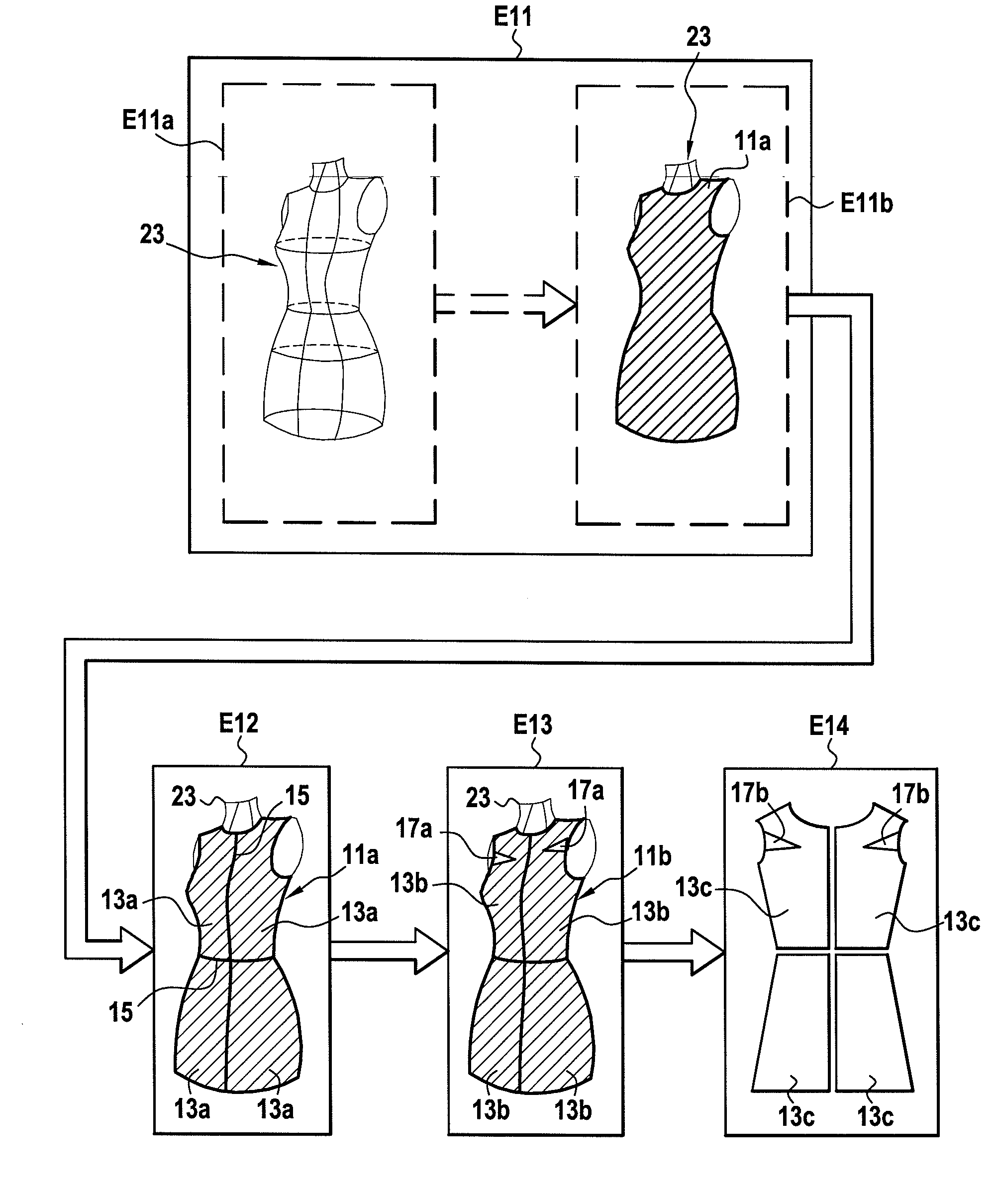
[0064]Generally speaking, the design of a garment starts with a sketch drawn by a stylist illustrating the model of the garment to be produced.

[0065]Subsequently, the patterners design the actual geometric shapes of the patterns and also the dimensions thereof in accordance with the various sizes of the garment. Thus, the patterner creates a block or base pattern which is most suitable for the model of the garment to be designed.

[0066]A base pattern is an initial or intermediate pattern, the shape of which is used at all times for the design of the garments. The base pattern is generally designed for an average-sized body of a target population.

[0067]The patterner is very adept at making the necessary modifications or transformations to the base patterns to obtain the model of the desired garment. For example, the patterner can modify the shape or the dimensions of a base pattern to attain the targeted model. A set of base patterns will be deemed to be suitable if the volume produce...


PUM


Abstract

The invention relates to a system and a method for the computer-aided design of a garment occupying a virtual surface represented by data stored in a memory of a computer including the following steps:generating base patterns (11a) on said virtual surface (13a),adding at least one style effect (17, 17a) on at least one base pattern (11a) transforming said at least one base pattern into at least one stylised base pattern (13b), andforming a stylised virtual surface (11b).

Description

TECHNICAL FIELD OF THE INVENTION[0001]The invention relates to the field of the computer-aided design (CAD) of a garment, and is used in particular in the clothing or sewing industries. More specifically, the invention describes a method and a device for the computer-aided design of garments comprising style effects.BACKGROUND TO THE INVENTION[0002]Currently, the computer-aided design of a garment is limited to the definition of patterns on a smooth surface which represents the surface of the garment surrounding a virtual mannequin and the laying-flat of the three-dimensional (3 D) surfaces which are created against a two-dimensional (2 D) surface.[0003]FIG. 17 illustrates the various steps for the computer design of a garment according to the prior art.[0004]In a first step E101, there is loaded into the computer a virtual garment surface 111 which may be a virtual mannequin or any other surface representing a skirt, trousers, sleeves, etc. The virtual garment surface 111 can be de...

Claims


Application Information

Patent Timeline
Patent Type & Authority Applications(United States)
IPC IPC(8): G06F19/00
CPCA41H3/007G06F2217/32G06F17/50G06F30/00G06F2113/12
Inventor LASTRA, JUAN JOSEYEPES, RAMON
Owner LECTRA SA (FR)
Why Eureka
Try Eureka