
Method and apparatus for monitoring web services resource utilization

a resource utilization and web service technology, applied in the field of dynamic adjustment of resources, can solve the problems of varying the amount of resources needed by every application, electronic equipment, and the difficulty of rationally adjusting resources among all applications

Inactive Publication Date: 2009-04-16
IBM CORP
View PDF8 Cites 24 Cited by
  • Summary
  • Abstract
  • Description
  • Claims
  • Application Information

AI Technical Summary

Benefits of technology

[0017]With the method and device provided by the present invention, resource consumption ratios of a plurality of co-existing applications can be obtained, and further, resource consumption of each of currently co-existing applications can be calculated according to the obtained resource consumption ratio, so that dynamically adjusting of resources is realized.
[0018]The present application is especially suitable for management of Web services on a Web server, and is of great significance for satisfaction with service level agreement of Web services and evaluation of Web services.

Problems solved by technology

However, the amount of resources needed by every application varies due to specific properties of every application, e.g. time complexity, space complexity and the like.
Thus, an electronic equipment wherein a plurality of applications co-exist is often faced with a difficult problem of how to rationally adjust resources among all applications.
Obviously, such a practice will cause part of resources to leave idle during normal running, thereby a waste phenomenon.
To meet the SLAS, the Web service providers often provide excess capacity when statically provisioning resources for their customers because it is hard to accurately predict demands, especially for the scenarios that some customers may occasionally experience a “web storm”, i.e. a dramatic temporary surge in demand.
For example, a particular web service may experience a heavy request volume caused by an emergent event.
The statically provisioned resources according to the average requirements can not deal with such a situation, which will cause the SLA violations.
If excess capacity is provided in order to meet the SLAs under various sudden conditions, a great cost of resources is thus paid, which is unacceptable to the Web service provider.
It is hard to provide resources consumed by each application respectively when multiple applications co-exist in one process or task.
Therefore, in this case, existing electronic equipment cannot dynamically adjust resources among each application in one process or task on the basis of the prediction of resource consumption amount.
Also, since the customers of commercial Grids pay for resources, they will not tolerate being denied service or being rescheduled to a different time slot, i.e., they will not tolerate the SLA violation.
Firstly, the SLA measurement can not indicate the root cause of the SLA violation, so that correct remedial measures can not be taken.
Secondly, even the detected SLA violation can be used for dynamically provisioning of the Web service, the SLA has already been violated and the customer has experienced the degraded quality of service before supplying the gap by allocating additional resources.

Method used


Image

  • Method and apparatus for monitoring web services resource utilization
  • Method and apparatus for monitoring web services resource utilization
  • Method and apparatus for monitoring web services resource utilization

Examples


first embodiment

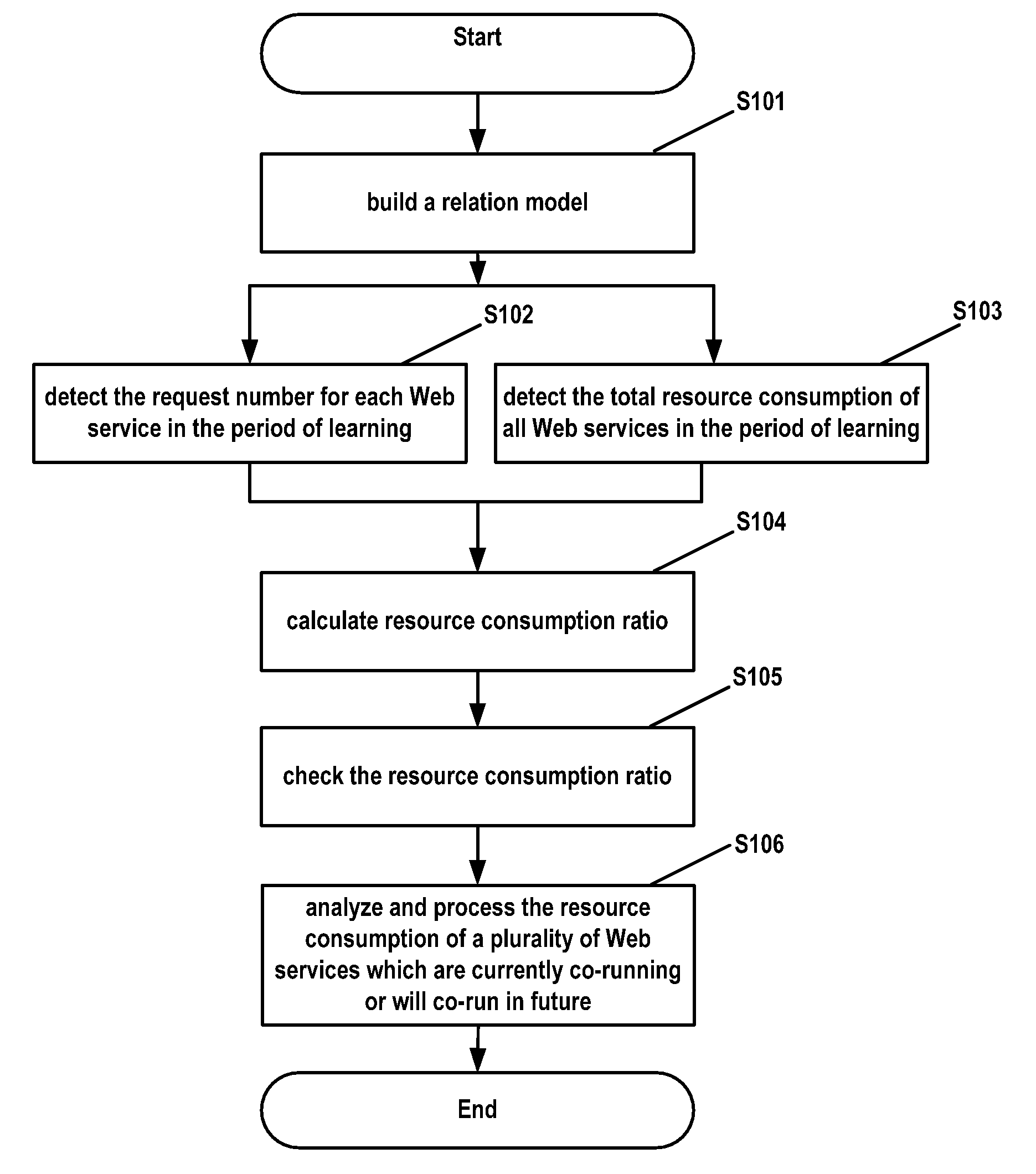
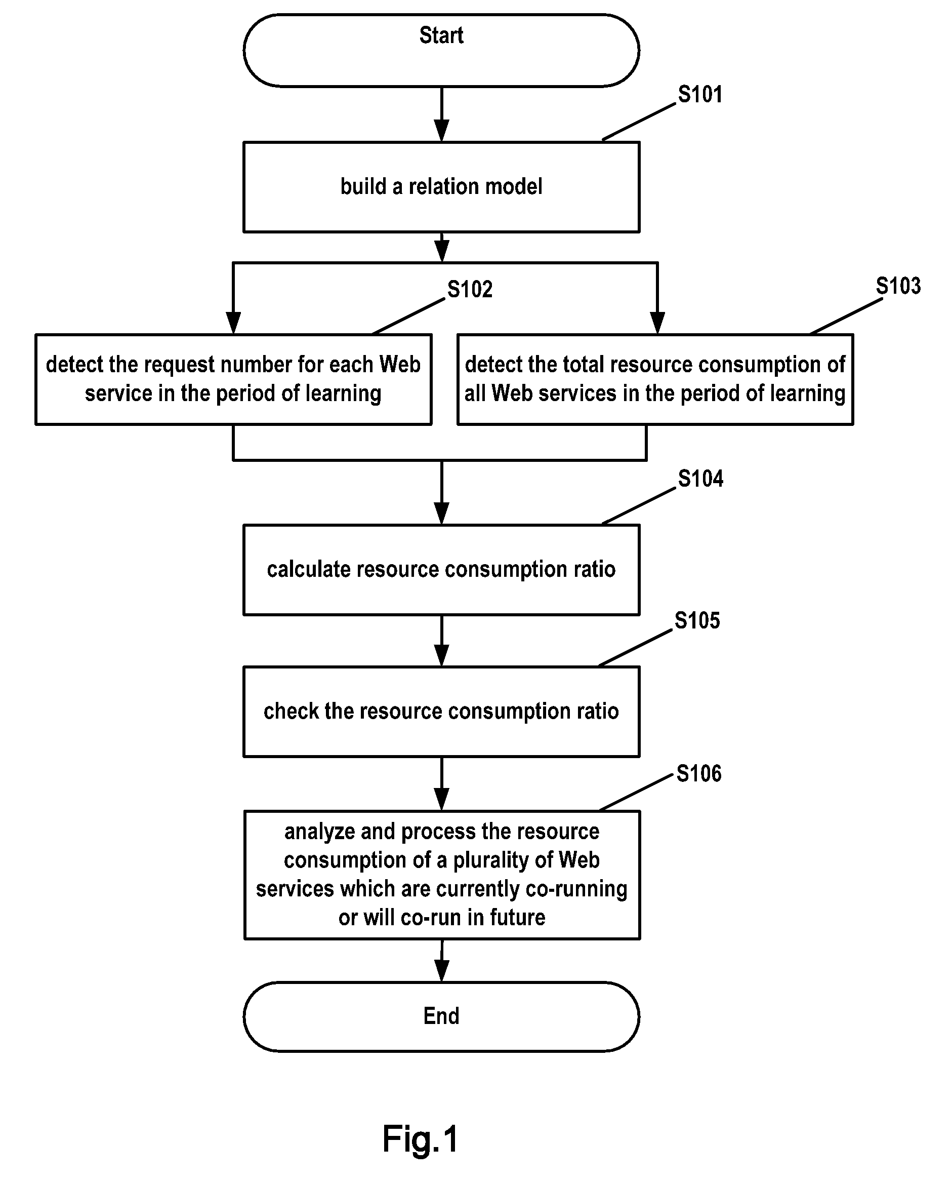
[0028]FIG. 1 is a flow chart of a method of dynamically adjusting resources according to the present invention.

[0029]As shown in FIG. 1, in step S101, a relation model on the relationship between request numbers of n Web services and resource consumptions of these Web services running on a Web server is established. Such a relation model is called Request Number Resource Consumption (RN-RC) relation model for short.

[0030]In the present embodiment, a linear statistic model is taken for example. As illustrated by expression (1), the linear statistic model uses different resource consumption ratios to represent the resource consumption ratio of each Web service:

Q=As1*Rs1+As2*Rs2+. . . +Asi*Rsi+. . . +Asn*Rsn+A0   (1)

[0031]In expression (1), Q represents the resource consumption of n Web services on the Web server; * represents multiplying relation; Asi is the resource consumption ratio of the (i)th Web service, which represents the ratio of resources on the Web server consumed by the (...

second embodiment

[0051]FIG. 4 schematically shows the structure of a device of dynamically adjusting resources according to the present invention. The device 400 of dynamically adjusting resources is used for dynamically adjusting resources for each Web service in the case that only the resource consumption of a plurality of Web services can be known. The device 400 of dynamically adjusting resources may be directly integrated into a Web server, or serve as an external separate device of a Web server.

[0052]The device 400 of dynamically adjusting resources as shown in FIG. 4 comprises: model building means 401, first detecting means 402, second detecting means 403, model learning means 404, resource consumption ratio checking means 405, analyzing means 406 and metric data storage means 407. The model building means 401 is used for building a relation model on the relationship between the resource consumption of n Web services co-existing on the Web server and the request number of each Web service, i...


PUM


Abstract

A method for dynamically adjusting resources among a plurality of co-existing applications comprises the steps of: building a relation model between a request number and resource consumption of said plurality of applications; obtaining at multiple sampling moments a request number and resource consumption of each of said plurality of applications; calculating resource consumption ratio of each of said plurality of applications; and analyzing resource consumption of a plurality of currently co-existing applications.

Description

FIELD OF THE INVENTION[0001]The present invention relates to the dynamic adjustment of resources among multiple co-existing applications.BACKGROUND OF THE INVENTION[0002]With the development of computer and network technology, it is a common sight nowadays that multiple applications co-exist on the same electronic equipment. For example, multiple applications co-exist on the same computer or multiple Web services are simultaneously provided on one Web server.[0003]Every application needs to occupy resources in an electronic equipment, such as central processing unit (CPU) resources, memory resources and the like. However, the amount of resources needed by every application varies due to specific properties of every application, e.g. time complexity, space complexity and the like. Thus, an electronic equipment wherein a plurality of applications co-exist is often faced with a difficult problem of how to rationally adjust resources among all applications.[0004]To guarantee normal runn...

Claims


Application Information

Patent Timeline
Patent Type & Authority Applications(United States)
IPC IPC(8): G06F15/173
CPCG06F9/5061G06F9/5083G06F2209/508G06F11/3447G06F2201/88G06F11/3433
Inventor CHEN, YINGLI, YINGQIU, JIE
Owner IBM CORP
Learn More