Hardware and Software Co-test Method for FPGA

a software and hardware co-testing technology, applied in the field of integrated circuits, can solve the problems of time-consuming traditional configuration of fpga, and achieve the effect of improving test efficiency

Inactive Publication Date: 2009-04-16
UNIV OF ELECTRONICS SCI & TECH OF CHINA +1
View PDF14 Cites 32 Cited by
  • Summary
  • Abstract
  • Description
  • Claims
  • Application Information

AI Technical Summary

Benefits of technology

[0018]The beneficial effect of the invention is that the test method is independent of FPGA type, array size and application, and can be utilized to test each IOB, CLB and routing matrix of FPGA automatically, exhaustively and repeatedly. As a result, test efficiency can be improved without handcraft.
[0019]These and other objectives, features, and advantages of the present invention will become apparent from the following detailed description, the accompanying drawings, and the appended claims.

Problems solved by technology

The technical barrier is that FPGA test time is determined by configuration numbers of FPGA consisting of a large amount of inherent and regular IOBs, CLBs and routing matrixes.
Traditional configuration for FPGA is time consuming due to the fact that the configuration has to be handcrafted.

Method used


Image

  • Hardware and Software Co-test Method for FPGA
  • Hardware and Software Co-test Method for FPGA
  • Hardware and Software Co-test Method for FPGA

Examples


Embodiment Construction

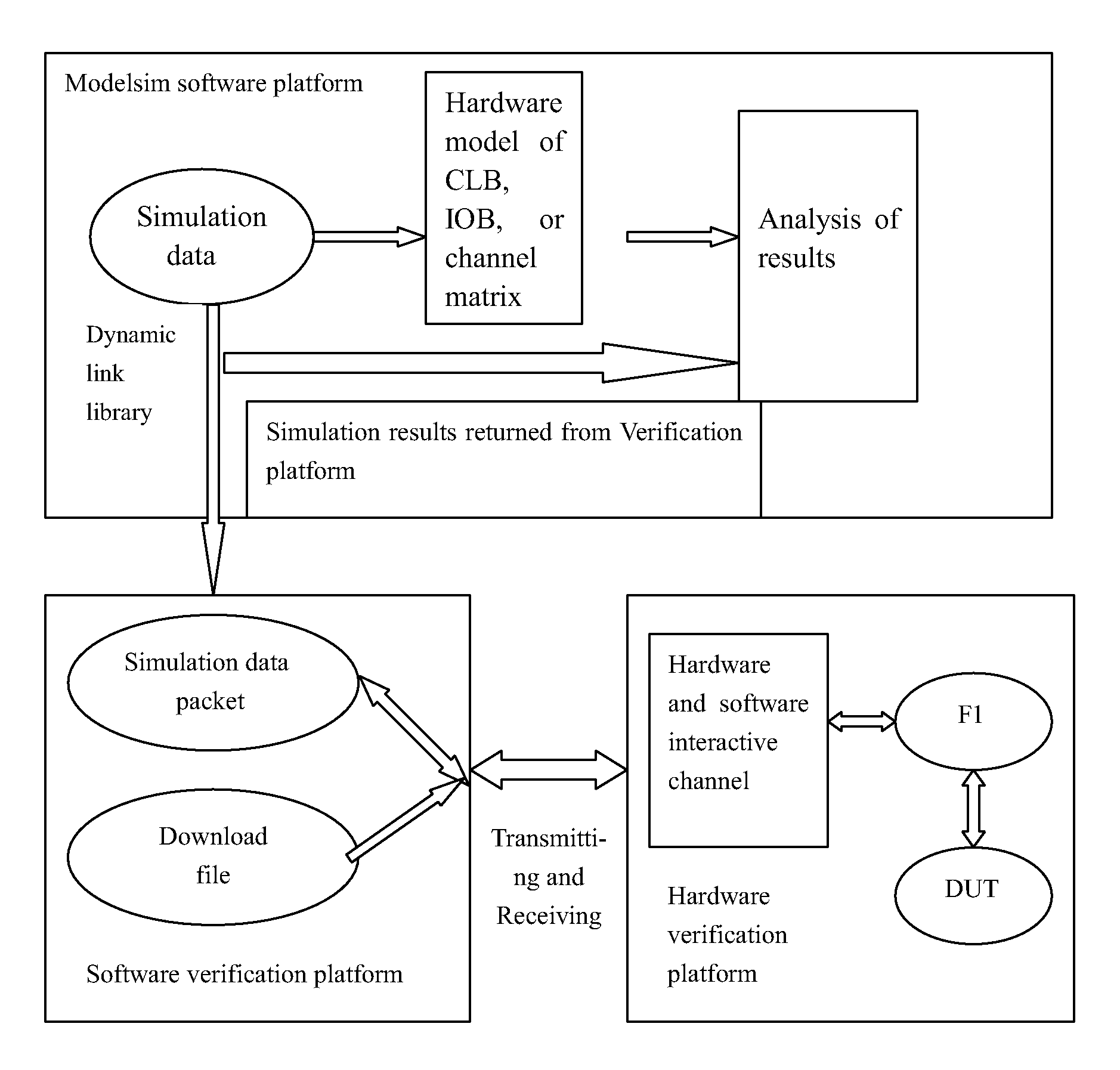
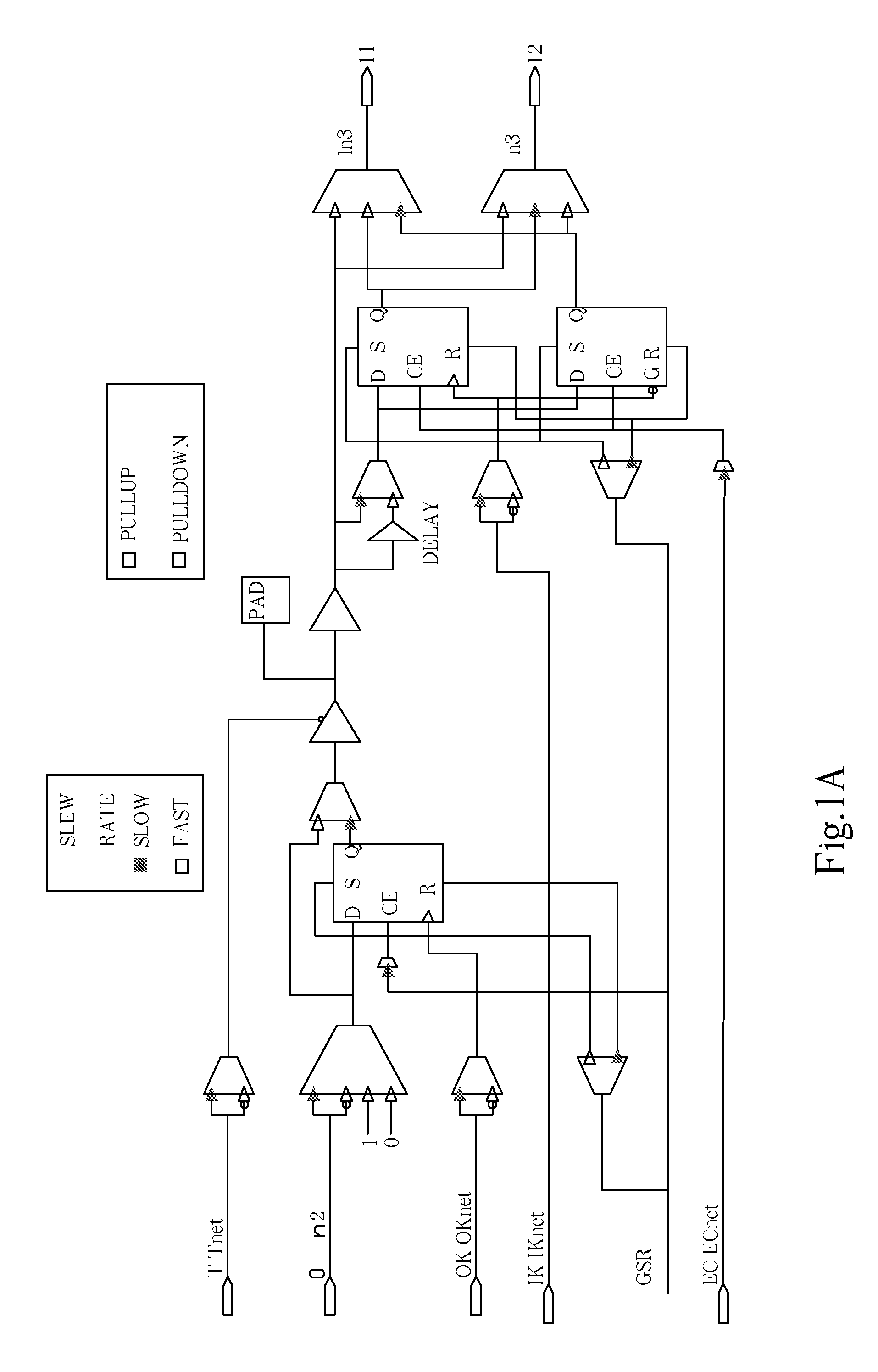
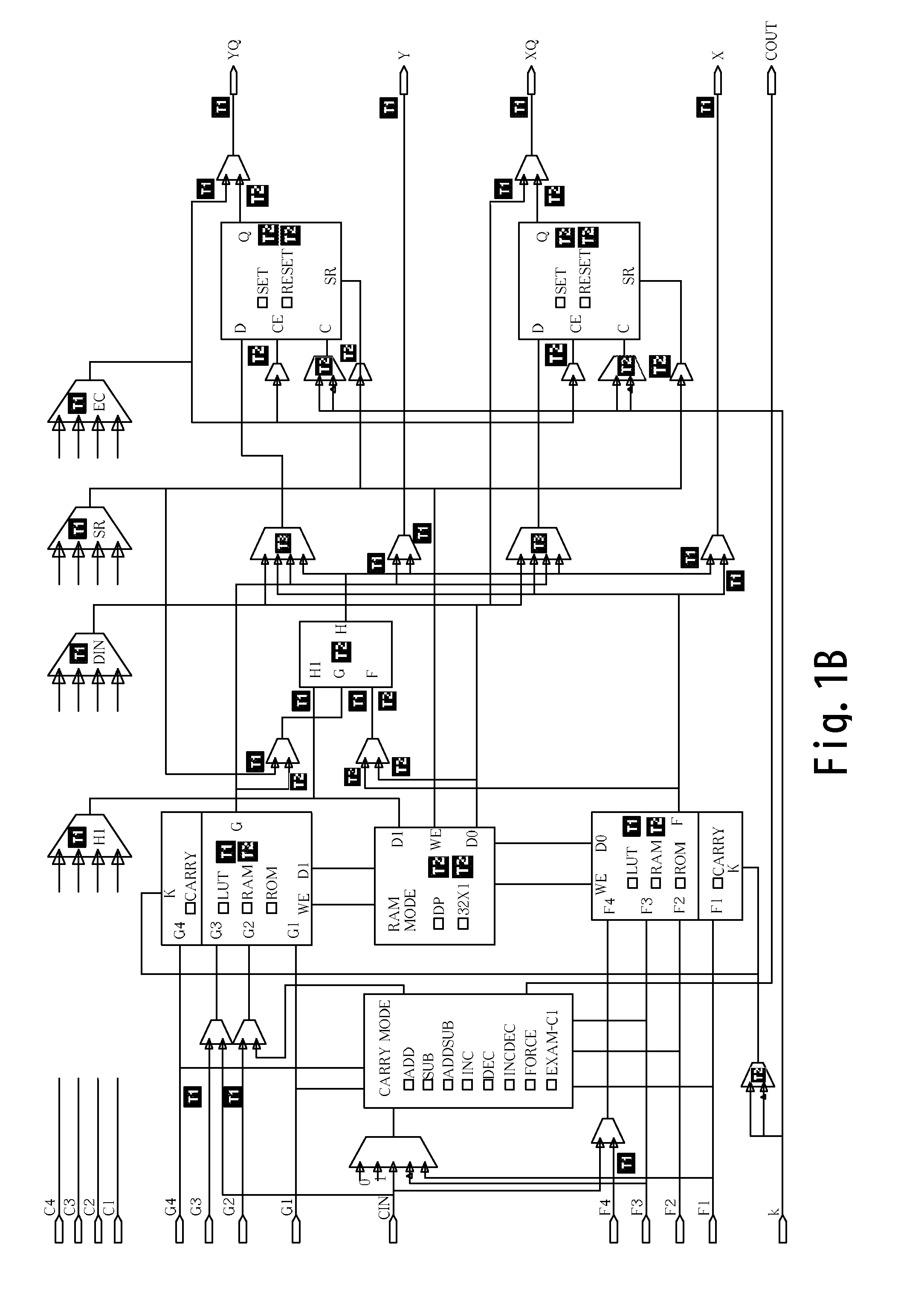
[0025]Referring to FIG. 1 and FIG. 2 of the drawings, a hardware / software co-test method for testing FPGA consisting of IOBs, CLBs and routing matrices comprises the following steps.

[0026]a. A HW / SW co-test system for FPGA consists of a PC, software part, HW / SW communication modules, a hardware accelerator and a DUT FPGA which is mapped with configuration file of DUT.

[0027]b. A table of test vectors for FPGA is predefined by software part in PC. In other words, a test vector is defined for each I / O module, CLB and routing matrix under test and is mapped with expected data.

[0028]c. The software part of the HW / SW co-test system for FPGA automatically generates configuration files one by one based on the tables of test vector for I / O module, CLB and routing matrix, and then sends the configuration file into DUT FPGA to configure the FPGA.

[0029]d. The DUT FPGA is tested by the HW / SW co-test system for FPGA in terms of the tables of test vector for I / O module, CLB and routing matrix. The...


PUM


Abstract

A hardware and software co-test method for FPGA comprises the following steps of: setting up a HW/SW co-test system comprising a PC, a software part, HW/SW communication modules, a hardware accelerator for testing a DUT FPGA which is mapped with a configuration file of DUT; predefining a table of test vectors for FPGA by software part in PC; generating configuration files based on the tables of test vector for I/O module, CLB and routing matrix, and then sending the configuration file into DUT FPGA to configure the FPGA; testing DUT FPGA in terms of the tables of test vector for lo I/O module, CLB and routing matrix, and returning results to the software part; and comparing the test results with expected data in the software part, generating a test report, and during the above steps, the error cells in the FPGA are capable of being automatically positioned.

Description

BACKGROUND OF THE PRESENT INVENTION [0001]1. Field of Invention[0002]The present invention relates to a test method for integrated circuits, and more particularly to a hardware and software co-test method for field programmable gate array (FPGA).[0003]2. Description of Related Arts[0004]A FPGA is composed of a large amount of CLBs, routing matrixes, and IOBs, each of which consists of logic gates, flip-flops (FFs) and control units. Edge-trigger FFs, latches, pull-up resisters are optional for the CLB, IOB and routing matrixes to control every block independently.[0005]A specific test suite has to be developed for each ASIC design due to different design and application for each ASIC. In contrast, FPGA is a generic device. What is more, a FPGA consists of a large amount of inherent and regular CLB, IOB and routing matrix. Therefore, functional test for FPGA is supposed to be uniform and independent of design and application.[0006]Currently, research for FPGA test mainly concentrates...

Claims


Application Information

Patent Timeline
Patent Type & Authority Applications(United States)
IPC IPC(8): G01R31/3177G06F11/25
CPCG01R31/318516
Inventor LI, PINGLIAO, YONGBORUAN, AIWULI, WEILI, WENCHANG
Owner UNIV OF ELECTRONICS SCI & TECH OF CHINA
Why Eureka
Try Eureka