Composite sensor

Inactive Publication Date: 2009-04-23
PANASONIC CORP
View PDF4 Cites 9 Cited by
  • Summary
  • Abstract
  • Description
  • Claims
  • Application Information

AI Technical Summary

Benefits of technology

[0008]In order to achieve the above and other objects, the present invention is a composite sensor provided with an external holding portion, an internal holding portion supported within the external holding portion via coupling portions, a vibration-type angular velocity sensor element, and an acceleration sensor element disposed within the internal holding portion, the composite senso

Problems solved by technology

However, it is not necessarily easy to package the both sensor elements integrally.
A separate attaching structure f

Method used


Image

  • Composite sensor
  • Composite sensor
  • Composite sensor

Examples


Example

[0016]Hereinafter, the best mode for carrying out the present invention will be described in detail with reference to the drawings.

[0017]One embodiment of the present invention will be described below using the drawings.

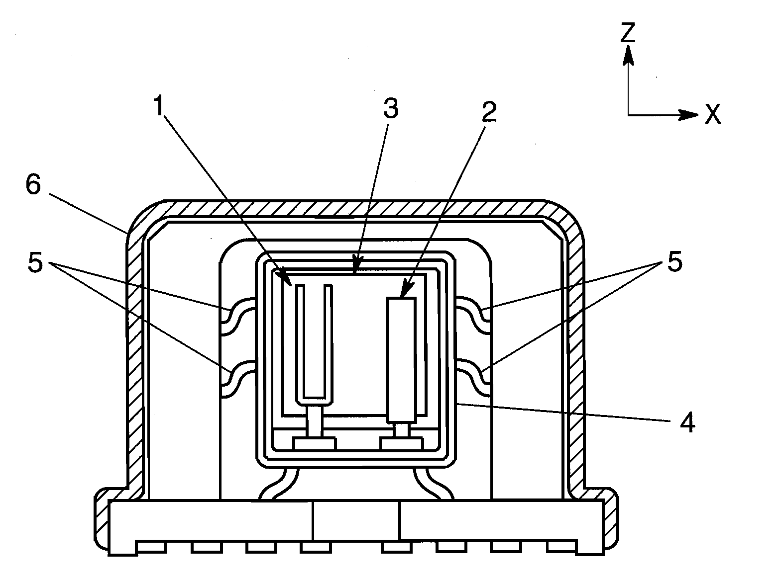
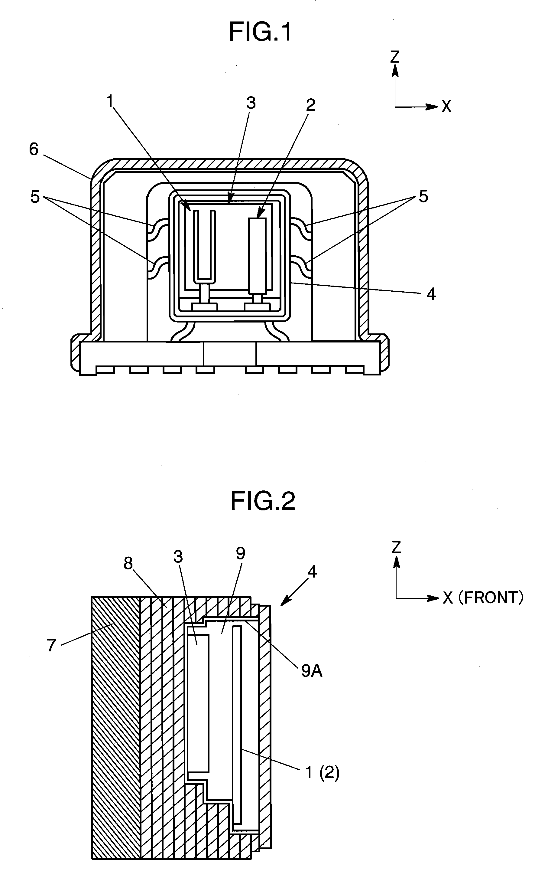
[0018]FIG. 1 shows a composite sensor in which a vibration-type angular velocity sensor element 1 and an acceleration sensor element 2 are integrated in one unit. In the descriptions below, X is defined as the right-left direction, Y as a direction perpendicular to the sheet surface, and Z as the top-bottom direction of the sheet surface of FIG. 1 for the descriptions regarding the directions in the drawing and the other respective drawings. Also, the right side of the sheet surface of FIG. 2 in the Y direction is tentatively defined as the front.

[0019]According to the basic structure of the composite sensor, the vibration-type angular velocity sensor element 1 and the acceleration sensor element 2, and an integrated circuit 3 as an example of a processing circuit th...


PUM


Abstract

A composite sensor includes an external holding portion 6, an internal holding portion 4 supported within the external holding portion 6 via coupling portion 5, and a vibration-type angular velocity sensor element 1 and an acceleration sensor element 2 disposed within the internal holding portion 4, and is configured so that the internal holding portion 4 is held in such a manner so as to substantially suppress a movement of the acceleration sensor element 2 along a detection direction while to allow a movement of the vibration-type angular velocity sensor element 1 in a direction in which it receives Coriolis force at least by an angular velocity. A reduction of the composite sensor in size can be achieved by this structure.

Description

TECHNICAL FIELD[0001]The present invention relates to a composite sensor equipped with a vibration-type angular velocity sensor element and an acceleration sensor element.BACKGROUND ART[0002]For a composite sensor of this type, there has been known a structure having an exterior package in which are disposed a vibration-type angular velocity sensor formed by packaging therein a vibration-type angular velocity sensor element and a signal processing circuit such as an IC, and an acceleration sensor formed by packaging therein an acceleration sensor element and a signal processing circuit thereof. As prior art reference information relating to the present application, for example, Patent Document 1 has been known.[0003]Patent Document 1: JP-A-2003-4450[0004]There has been an increasing need for such a composite sensor to further reduce the size as a system incorporating such composite sensors becomes more compact and expands in functionality. A possible structure to meet this need is t...

Claims


Application Information

Patent Timeline
IPC IPC(8): G01P9/04G01C19/56
CPCG01C19/56G01P15/097G01P15/09G01P1/023
Inventor OHKOSHI, HIDEO
Owner PANASONIC CORP
Why Eureka
Try Eureka