Apparatus for cleaning tube fins of air fan cooler for heat exchanger

a technology for air fan coolers and fan fins, which is applied in the direction of cleaning heat-transfer devices, cleaning using liquids, trickle coolers, etc., can solve the problems of deteriorating air-conditioning operation efficiency, and affecting the cleaning effect of the cooling fan. achieve the effect of environmental protection

Inactive Publication Date: 2009-04-23
SK ENERGY CO LTD (KR)
View PDF4 Cites 13 Cited by
  • Summary
  • Abstract
  • Description
  • Claims
  • Application Information

AI Technical Summary

Benefits of technology

[0011]The present invention has been made in an effort to provide an apparatus for cleaning tube fins of an air fan cooler for heat exchangers which can clean the tube fins even when the air fan cooler is in operation. In the cleaning process, the tube fins are prevented from becoming damaged, and environment-friendly cleaning can be conducted.
[0012]The present invention provides an apparatus for cleaning tube fins of an air fan cooler for heat exchangers which is constructed such that the cleaning operation of removing dust from the tube fins can be conducted even when the air fan cooler is in operation, thus preventing the heat exchange efficiency of the tube fins from becoming reduced by dust.
[0013]Furthermore, the present invention provides an apparatus for cleaning tube fins of an air fan cooler for heat exchangers which can prevent the tube fins from becoming partially damaged or corroded during the process of removing dust from the tube fins.
[0014]In addition, the present invention provides an apparatus for cleaning tube fins of an air fan cooler for heat exchangers which restrains from the use of chemicals, thus allowing environment-friendly cleaning.

Problems solved by technology

Meanwhile, such tube fins become covered with a lot of dust while conducting heat exchange.
The heat exchange efficiency of the tube fins may deteriorate due to the dust, with the result that the operation efficiency of the air fan cooler deteriorates, thus inducing a failure of the production of products.
However, the operation of cleaning the tube fins using chemicals is disadvantageous in that only when the air fan cooler is not in operation can the cleaning operation be conducted.
Therefore, it is inefficient.
In addition, the cleaning operation and a preparatory process therefor are very complex.
Moreover, in the case where chemicals are used for a long period of time, the tube fins made of aluminum may corrode, thus causing secondary damage.
As well, there is a problem in that chemicals induce air and water pollution.

Method used


Image

  • Apparatus for cleaning tube fins of air fan cooler for heat exchanger
  • Apparatus for cleaning tube fins of air fan cooler for heat exchanger
  • Apparatus for cleaning tube fins of air fan cooler for heat exchanger

Examples


Embodiment Construction

[0022]Hereinafter, an embodiment of the present invention will be described in detail with reference to the attached drawings.

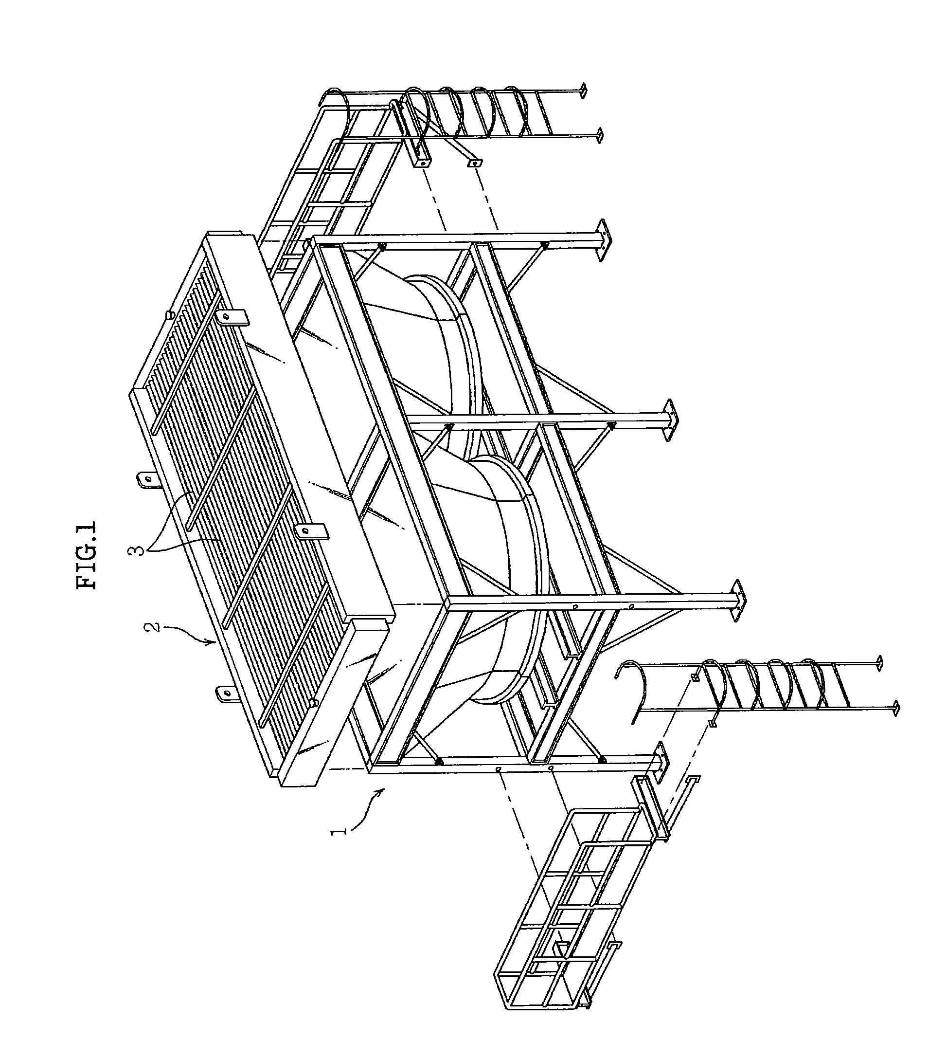
[0023]FIG. 1 is an exploded perspective view illustrating an embodiment of an air fan cooler for heat exchangers according to the present invention, in which tubes having fins are installed on the air fan cooler.

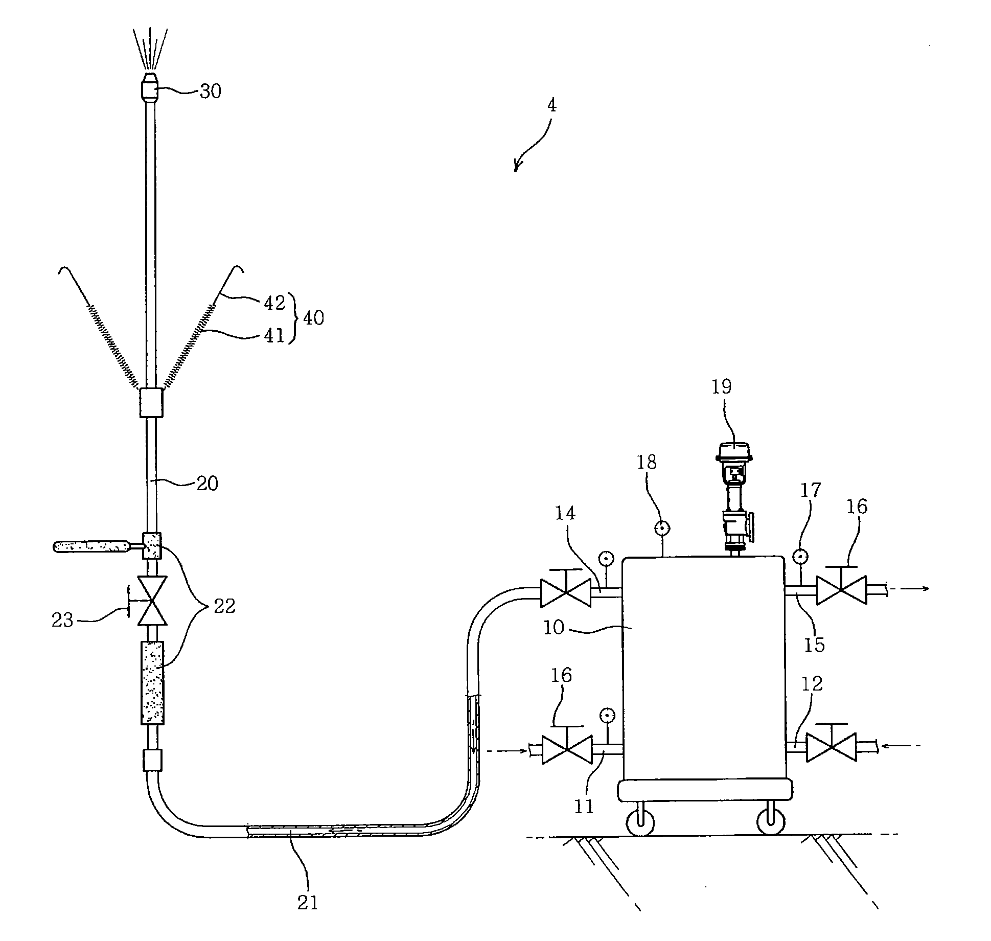
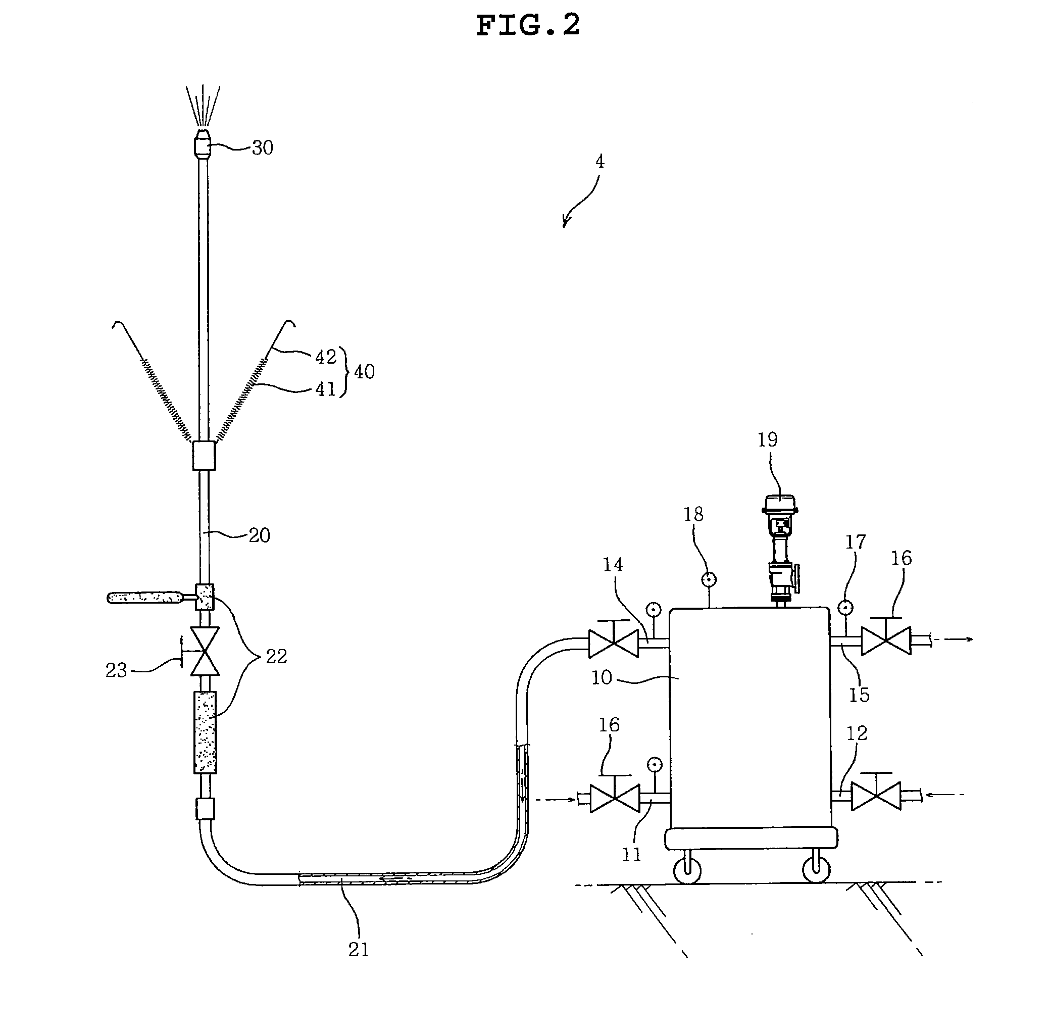
[0024]FIG. 2 is a schematic view of an embodiment of a cleaning apparatus according to the present invention to illustrate the construction and connection of the cleaning apparatus, which jets steam containing condensate onto the tube fins of the air fan cooler to remove dust from the tube fins.

[0025]FIG. 3 is a schematic view illustrating an embodiment of a condensate generator according to the present invention. In detail, FIG. 3 schematically shows the condensate generator, which generates condensate using heat exchange between steam and cooling water, and to which a thermometer for measuring temperatures of the supplied steam and cooling water, an...


PUM


Abstract

Disclosed herein is an apparatus for cleaning tube fins of an air fan cooler for heat exchangers. The apparatus according to the present invention is constructed such that the tube fins can be cleaned in a mechanical manner even when the air fan cooler is in operation, thus preventing the heat exchange efficiency of the tube fins from becoming reduced by dust. Furthermore, the present invention restrains the use of chemicals, thus realizing environment-friendly cleaning.

Description

CROSS REFERENCE TO RELATED APPLICATION[0001]This application claims the benefit of Korean Patent Application No. 10-2007-0106279, filed Oct. 22, 2007, entitled “AIR FAN COOLER TUBE FIN ONLINE CLEANING PACKAGE FOR HEAT EXCHANGER”, which is hereby incorporated by reference in its entirety into this application.BACKGROUND OF THE INVENTION[0002]1. Field of the Invention[0003]The present invention relates generally to apparatuses for cleaning tube fins of air fan coolers for heat exchangers and, more particularly, to an apparatus for cleaning tube fins of an air fan cooler for heat exchangers which is constructed such that the tube fins can be cleaned in a mechanical manner even when the air fan cooler is in operation, thus preventing the heat exchange efficiency of the tube fins from becoming reduced by dust, and cleaning of which restrains from the use of chemicals, thus realizing environment-friendly cleaning.[0004]2. Description of the Related Art[0005]Generally, tube fins of an air ...

Claims


Application Information

Patent Timeline
Patent Type & Authority Applications(United States)
IPC IPC(8): B08B3/02
CPCB08B3/02F28G1/166B08B2230/01B08B3/026F28C1/00
Inventor KIM, YOUNG CHEOLGO, JAE SIKPARK, JAE HONGHONG, BEONG HOLEE, WANG CHUNKIM, HYO JOONYOON, HYUN JIN
Owner SK ENERGY CO LTD (KR)
Why Eureka
Try Eureka