Method and Device for Securely Loading and Mounting a Tubular Device in a Flexible Wall and Manufacturing Method for said Loading Device

Active Publication Date: 2009-04-23
COLOPLAST AS
View PDF8 Cites 15 Cited by
  • Summary
  • Abstract
  • Description
  • Claims
  • Application Information

AI Technical Summary

Benefits of technology

[0011]The present invention provides the advantage over the prior art that it offers improved security of the mounting process, in combination with improved user-friendliness and a ready to use self contained device.

Problems solved by technology

Potential sources of errors are for instance the orientation of the retainers when loaded into the loading tube, the rotational orientation of the tubular device in the loading tube and thus in the flexible wall when mounted into the wall, or contamination of the tubular device with undesired contaminants.

Method used


Image

  • Method and Device for Securely Loading and Mounting a Tubular Device in a Flexible Wall and Manufacturing Method for said Loading Device
  • Method and Device for Securely Loading and Mounting a Tubular Device in a Flexible Wall and Manufacturing Method for said Loading Device
  • Method and Device for Securely Loading and Mounting a Tubular Device in a Flexible Wall and Manufacturing Method for said Loading Device

Examples


Embodiment Construction

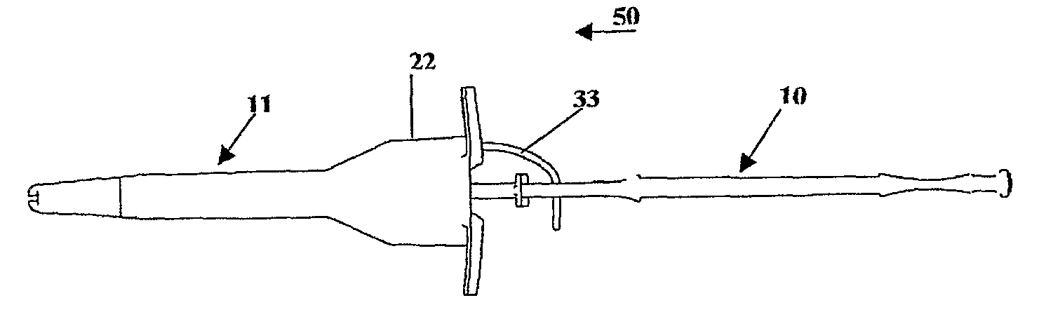
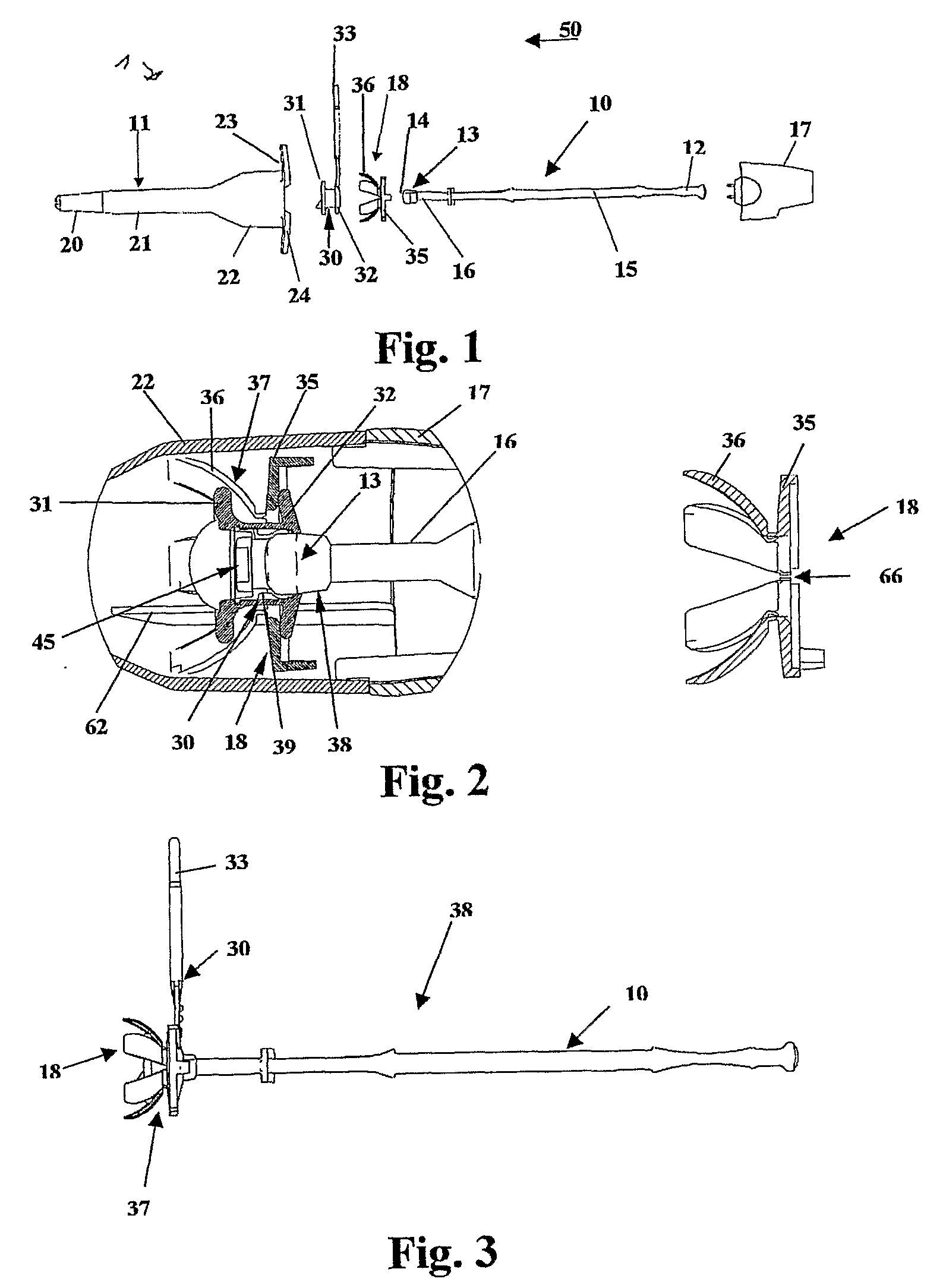
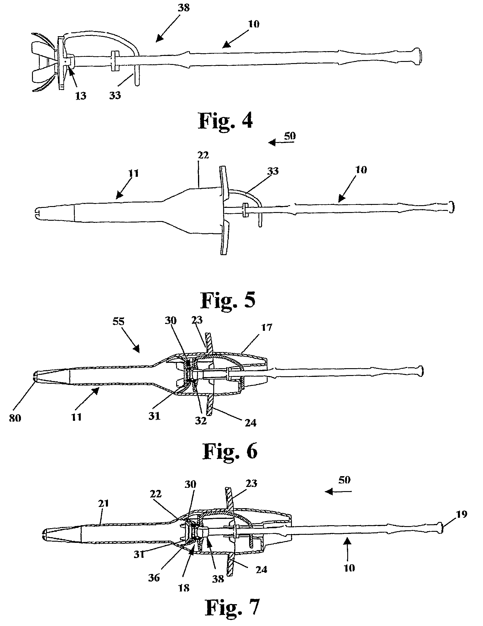
[0052]In FIG. 1 the components of a loading device according to a first embodiment for practising a method according to the invention are shown. The loading device is a tool for inserting a bushing 30 into a flexible wall, comprising an inserter 10 constructed as an elongate shank, a loading tube 11, a bending member 18, and a rear guiding cover 17, all of a plastics material or any other suitable material.

[0053]The loading tube 11 comprises an introduction section 22 narrowing in insertion direction 50 into an elongate delivery section 21 ending in a tip section 20. At the end opposite to tip 20, two gripping appliances 23, 24 are arranged transversally on the loading tube 11.

[0054]The inserter 10 has at one end thereof a handle 12 adapted to applying an axial force pushing the inserter into the loading tube 11, and at the other end a cylindrical head 13 including a conically bevelled end portion 14. Between the handle and the head the inserter forms adjacent the handle a flat port...


PUM

PropertyMeasurementUnit
flexibleaaaaaaaaaa
threshold resistanceaaaaaaaaaa
release forceaaaaaaaaaa

Abstract

An improved method and device for securely inserting a tubular element (30) into a through-aperture (40) in a flexible wall (60) accessible from one side only. The tubular element has a retainer (31, 32) projecting transversely at each end thereof, said retainer being resiliently foldable towards the axis of said tubular element. The element is inserted into a loading tube (11), wherein the retainers are automatically folded into the correct orientation by an automatic bending means (18). The bending means is part of a self-contained device for inserting said tubular element (30) into said through-aperture (40).

Description

FIELD OF THE INVENTION[0001]The invention pertains in general to a method and a device for inserting a tubular element having a retainer projecting transversely at each end thereof, said retainer being resiliently foldable towards the axis of said tubular element, into a through aperture in a flexible wall accessible from one side only. Furthermore, the invention concerns a method of manufacturing such a device.BACKGROUND OF THE INVENTION[0002]There may be a need of mounting in products of flexible material such as inflatable objects, or hoses of coated fabric or rubber material, tubular elements of different kinds for example bushings, connectors, or valves, in a flexible wall which is accessible from one side only.[0003]EP-B1-0868291 discloses a method and device for mounting a tubular element in a flexible wall using a loading tube and a tool inserted therein supporting the tubular element during delivery through the loading tube. Although the method and device are well proven fo...

Claims


Application Information

Patent Timeline
Patent Type & Authority Applications(United States)
IPC IPC(8): F16B17/00B23P11/02A61FA61F2/20
CPCA61F2/203Y10T29/53709Y10T29/49863A61F2/20F16B17/006F16L41/00B29C65/56
Inventor KARLING, JONASMARGOLIN, GREGORY
Owner COLOPLAST AS
Why Eureka
Try Eureka