Valve combination structure with front pressure reducer

A combined structure and pressure reducer technology, applied in the aerospace field, can solve problems such as launch mission failure and easy failure

Active Publication Date: 2021-03-30
BEIHANG UNIV
View PDF10 Cites 4 Cited by
  • Summary
  • Abstract
  • Description
  • Claims
  • Application Information

AI Technical Summary

Problems solved by technology

[0004] In order to overcome the deficiencies in the prior art, this application provides a valve combination structure with the pressure reducer in front, which is used to solve the problem in the prior art that the connecting pipelines often adopt stainless steel welded structures, which are prone to failure under high pressure and vibration environments , a technical problem that caused the launch mission to fail

Method used


Image

  • Valve combination structure with front pressure reducer
  • Valve combination structure with front pressure reducer
  • Valve combination structure with front pressure reducer

Examples


Embodiment 1

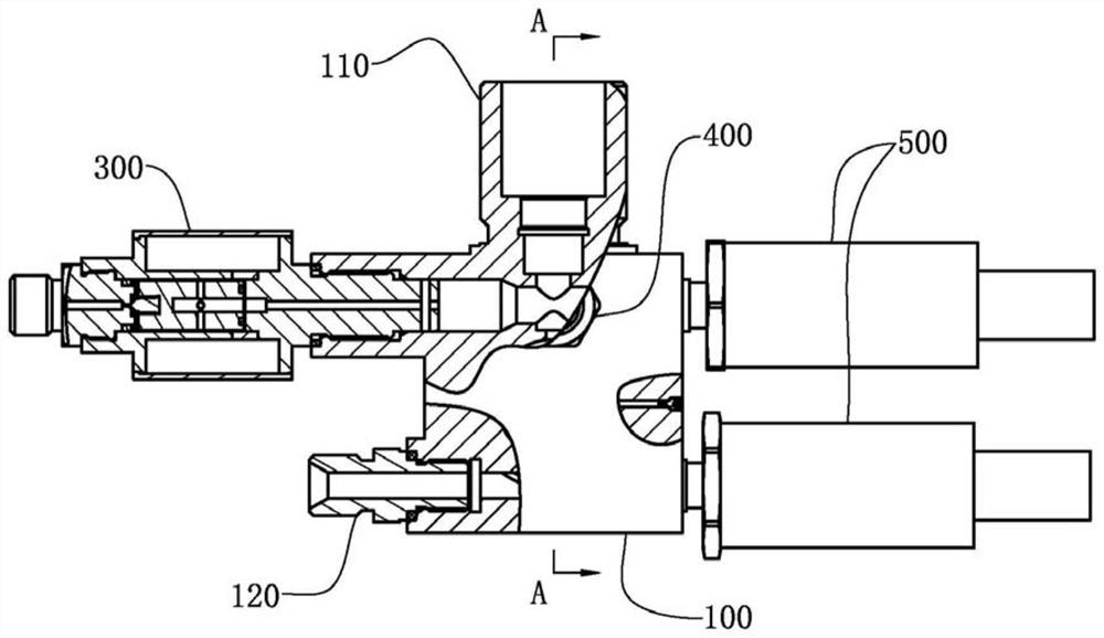
[0057] see Figure 1 to Figure 7 , the present embodiment provides a pressure reducer in front of the valve combination structure, which is applied to the extrusion conveying system of the rocket engine. Through the integrated combination method, the welding structure is reduced, and the installation process of the gas pipeline valve is improved. Improve the reliability of the system.

[0058] The rocket engine extrusion conveying system also includes a gas cylinder and a storage tank. The gas cylinder and the storage tank are connected by a valve combination structure in front of the pressure reducer. The gas cylinder is used to provide gas, and the valve combination in front of the pressure reducer The structure is used to control the output gas pressure of the gas cylinder, and then control the pressure of the air pillow of the storage tank.

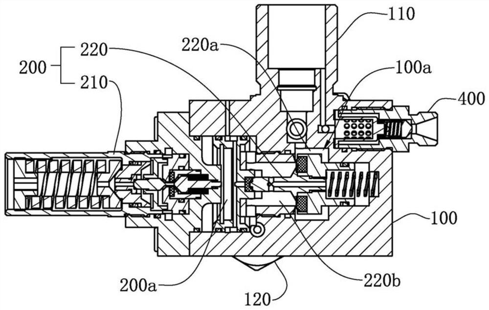
[0059] Please refer to figure 1 and figure 2 The combined structure of the pressure reducer provided in this embodiment includes...


PUM


Abstract

The invention provides a valve combination structure with a front pressure reducer, and relates to the technical field of aerospace. The valve combination structure with the front pressure reducer comprises a base body, the pressure reducer, a remote pressure relief valve and a pressurizing one-way valve, wherein the pressure reducer, the remote pressure relief valve and the pressurizing one-way valve are arranged on the base body; the base body is further provided with a gas cylinder connector and a gas outlet nozzle, the gas cylinder connector and the gas outlet nozzle communicate through agas flow cavity in the base body, the gas cylinder connector is used for being connected with a gas cylinder, and the gas outlet nozzle is used for exhausting gas entering the gas flow cavity from thegas cylinder; the pressure reducer is used for controlling the pressure of the gas exhausted by the gas outlet nozzle; the remote pressure relief valve is used for remotely relieving the pressure ofthe gas cylinder; and the pressurizing one-way valve is used for pressurizing the gas cylinder. According to the valve combination structure with the front pressure reducer, the pressure reducer, theremote pressure relief valve and the pressurizing one-way valve are integrated with the gas cylinder connector and the gas outlet nozzle through the base body, that is, the base body is shared to forma combination valve, a welding structure is omitted, the mounting process of a gas circuit pipeline valve is improved, and the reliability of a system is improved.

Description

technical field [0001] The invention relates to the field of aerospace technology, in particular to a valve combination structure with a pressure reducer in front. Background technique [0002] The rocket engine extrusion conveying system often uses a pressure reducer to control the pressure of the air pillow in the storage tank. The functional components in the valves of the gas pipeline are independently set and connected through the connecting pipeline. [0003] Since each valve assembly in the rocket engine is set independently, the connecting pipeline often adopts stainless steel welded structure to realize the connection between each valve assembly. However, the stainless steel welded structure is prone to failure under high pressure and vibration environment, resulting in the failure of the launch mission. Contents of the invention [0004] In order to overcome the deficiencies in the prior art, this application provides a valve combination structure with the pressu...

Claims


Application Information

Patent Timeline
Patent Type & Authority Applications(China)
IPC IPC(8): F16K17/20F17D3/01
CPCF16K17/20F17D3/01
Inventor 张源俊朱浩李志罗颢文彭荀
Owner BEIHANG UNIV
Why Eureka
Try Eureka