Connector having coupling guides for establishing connection with memory connector at right position

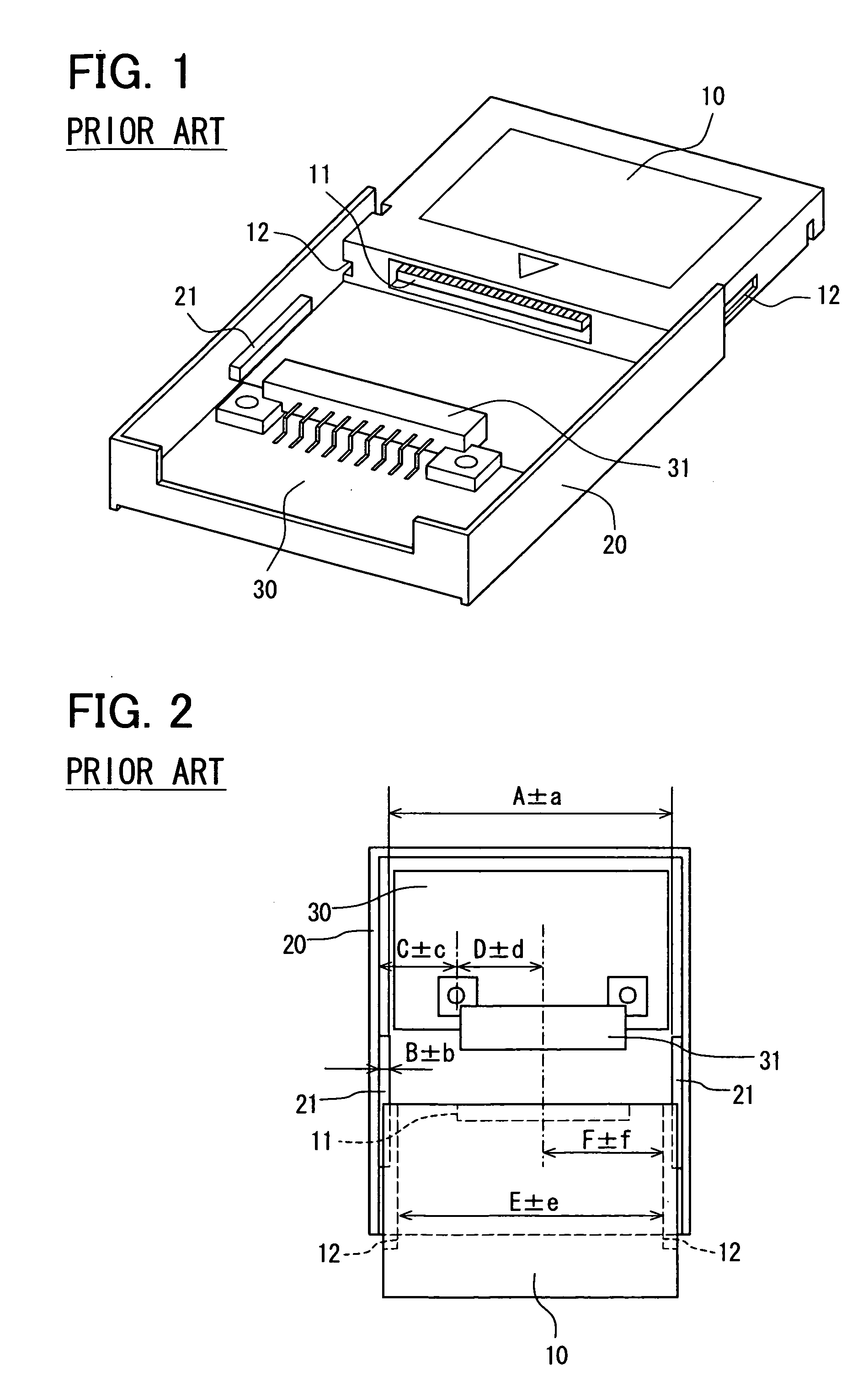
a technology of memory connector and coupling guide, which is applied in the direction of incorrect coupling prevention, coupling device connection, electrical apparatus, etc., can solve the problems of imposing an excessive force on the soldered position of the terminal, and affecting the correct coupling of the two connectors

Inactive Publication Date: 2009-04-23
DENSO CORP
View PDF2 Cites 21 Cited by
  • Summary
  • Abstract
  • Description
  • Claims
  • Application Information

AI Technical Summary

Benefits of technology

[0010]The present invention has been made in view of the above-mentioned problems, and an object of the present invention is to provide an improved connector that can be correctly coupled to another connector installed in a memory device.
[0011]The connector of the present invention is disposed in a casing containing an electronic device such as a car navigation device. The connector is coupled to a memory side connector installed in a memory device such as a hard disc. The connector includes a support member having a back plate and a pair of side plates connected to the back plate. The connector is disposed on the back plate, and coupling guides integrally formed with the support member are disposed on the side plates. The coupling guides are coupled to guiding grooves formed on the memory device, to thereby position the connector correctly relative to the memory-side connector.
[0013]In addition to the coupling guides, additional guides to be coupled to additional guiding structures formed on the memory device may be made in the vicinity of the coupling guides to thereby further improve positional matching between two connectors. A floating structure for adjusting a positional relation between the connector and the memory-side connector may be disposed between both connectors.

Problems solved by technology

This causes fault electrical connections or imposes an excessive force on soldered positions of the terminals.
However, some problems are involved in those proposed devices.
Because of these deviations, two connectors may not be coupled correctly at a right position.
Therefore, there is a possibility that connectors may not be coupled to each other because of excessive dimensional deviations of components.
In addition, the device becomes expensive because the separate guiding member has to be provided.

Method used


Image

  • Connector having coupling guides for establishing connection with memory connector at right position
  • Connector having coupling guides for establishing connection with memory connector at right position
  • Connector having coupling guides for establishing connection with memory connector at right position

Examples


Embodiment Construction

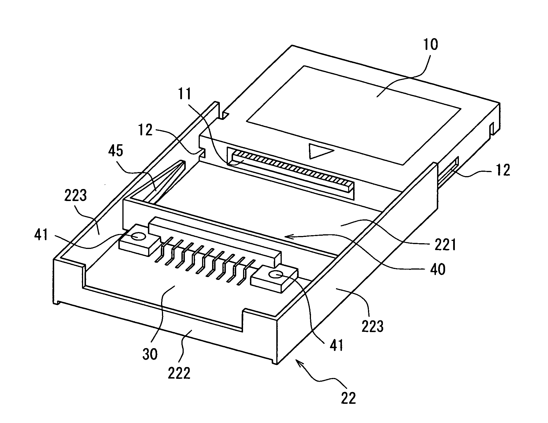
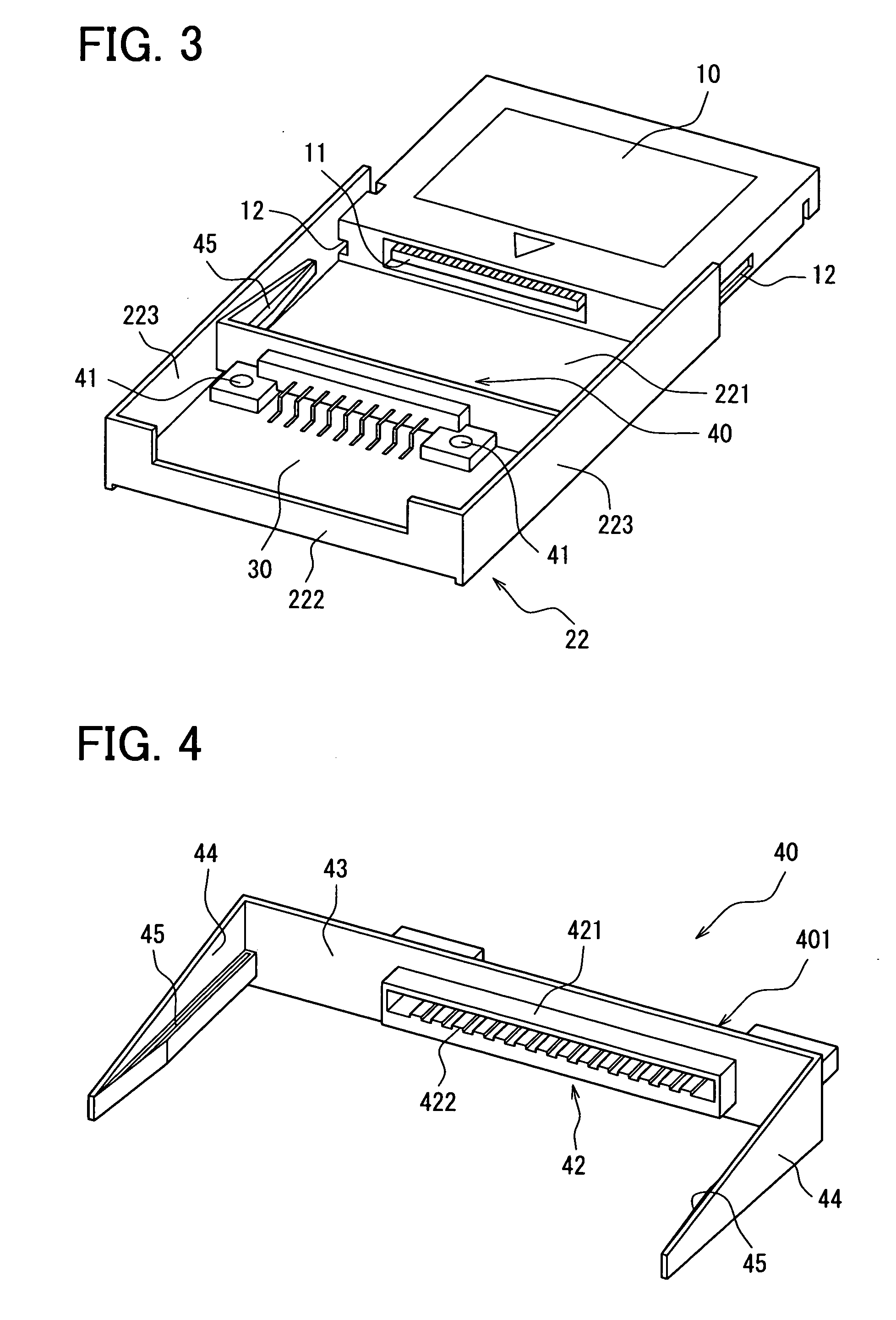
[0024]A preferred embodiment of the present invention will be described with reference to FIGS. 3 and 4. First, referring to FIG. 3, a connector 40 to be coupled to another connector 11 (referred to as a memory-side connector) installed in a memory device 10 such as a hard disc will be described. The hard disc may be replaced with a USB memory. The connector 40 is mounted on a casing 22 containing an electronic device such as a car navigation device. The connector 40 has plural terminals to be coupled and electrically connected to the memory-side connector 11.

[0025]The casing 22 is composed of an end wall 222, a bottom wall 221 and a pair of sidewalls 223 connected to the end wall 222 and the bottom wall 221 at a right angle. An opposite side to the end wall 222 is an opening through which the memory device 10 is slidably coupled to the casing 22. The connector 40 composed of a support member 401 and a coupler 42 containing terminals 422 (refer to FIG. 4) is mounted on the casing 22...


PUM


Abstract

A connector installed in a casing containing an electronic device such as a car navigation device is coupled to another connector installed in a memory device such as a hard disc. The connector includes a support member composed of a back plate and side plates connected to the back plate. The connector is disposed on the back plate, and coupling guides to be coupled to guiding grooves formed on the memory device are formed integrally with the side plates. The coupling guides are slid into the guiding grooves to correctly position the connector relative to the memory-side connector when the memory device is coupled to the casing containing the connector. Thus, the connector is surely coupled to the memory-side connector at a right position to establish electrical connection between two connectors.

Description

CROSS-REFERENCE TO RELATED APPLICATION[0001]This application is based upon and claims benefit of priority of Japanese Patent Application No. 2007-274299 filed on Oct. 22, 2007, the content of which is incorporated herein by reference.BACKGROUND OF THE INVENTION[0002]1. Field of the Invention[0003]The present invention relates to a connector having coupling guides for establishing connection with a second connector (a connector installed in a memory connector) at a right position.[0004]2. Description of Related Art[0005]A connector installed in an electronic device such as a car navigation system is often connected to another connector of a memory device such as a hard disc. A guide for connecting two connectors at a right position is conventionally provided. An example of a conventional connector having such a guide is shown in FIGS. 1 and 2 attached hereto. A pair of coupling guides 21 is provided in a casing 20 that contains a connector 31 therein. A pair of guiding grooves 12 is ...

Claims


Application Information

Patent Timeline
Patent Type & Authority Applications(United States)
IPC IPC(8): H01R13/64
CPCH01R13/631H01R12/7005H01R13/6315
Inventor MATSUZAWA, HIROKI
Owner DENSO CORP
Why Eureka
Try Eureka